Bulkhead anchor for medical device leads

a technology for medical devices and anchors, applied in the field of anchors for leads, can solve the problems of increasing the risk of lead damage, and reducing the safety of lead anchors, so as to maintain robust anchoring performance and reduce or eliminate the damage of leads.

Pending Publication Date: 2022-05-26
ADVANCED NEUROMODULATION SYST INC
View PDF5 Cites 0 Cited by
  • Summary
  • Abstract
  • Description
  • Claims
  • Application Information

AI Technical Summary

Benefits of technology

[0013]Embodiments of bulkhead anchors are configured to reduce or eliminate damage to the leads while maintaining robust anchoring performance. For example, bulkhead anchors configured according to concepts of the present invention provide a tight friction interface between the anchor and the lead without introducing sharp concentrated shear forces on the lead that can be stress points. In operation of bulkhead anchors of embodiments, compressive forces are distributed substantially equally around the lead body, such as by the flexure finger members relatively uniformly squeezing the lead around a portion at which the anchor is disposed.

Problems solved by technology

Retaining the implanted therapy delivery element in the desired location also creates difficulties because the location may change over time as the patient moves.
Current lead designs, however, are often prone to movement (e.g., axially, radially and / or longitudinally) after insertion if steps are not taken to control such movement.
Existing techniques for securing anchors to the lead body can be problematic.
Such an interface may, however, provide non-uniform force around the periphery of the lead body where interfaced with the anchor.
Such concentrated forces on the lead can be stress points that can result in damage to some configurations of leads.
RF shielded lead configurations may not be particularly well suited for accommodating a compressive force concentrated at a particular point.
For example, stress points introduced upon a lead body by an anchor may damage the braided shielding and / or polymer outer sheath of a lead.
Such damage may manifest as the sheath material being scraped away to expose the braiding and / or the braiding deforming under the anchor clamping load.

Method used


Image

  • Bulkhead anchor for medical device leads
  • Bulkhead anchor for medical device leads
  • Bulkhead anchor for medical device leads

Examples


Embodiment Construction

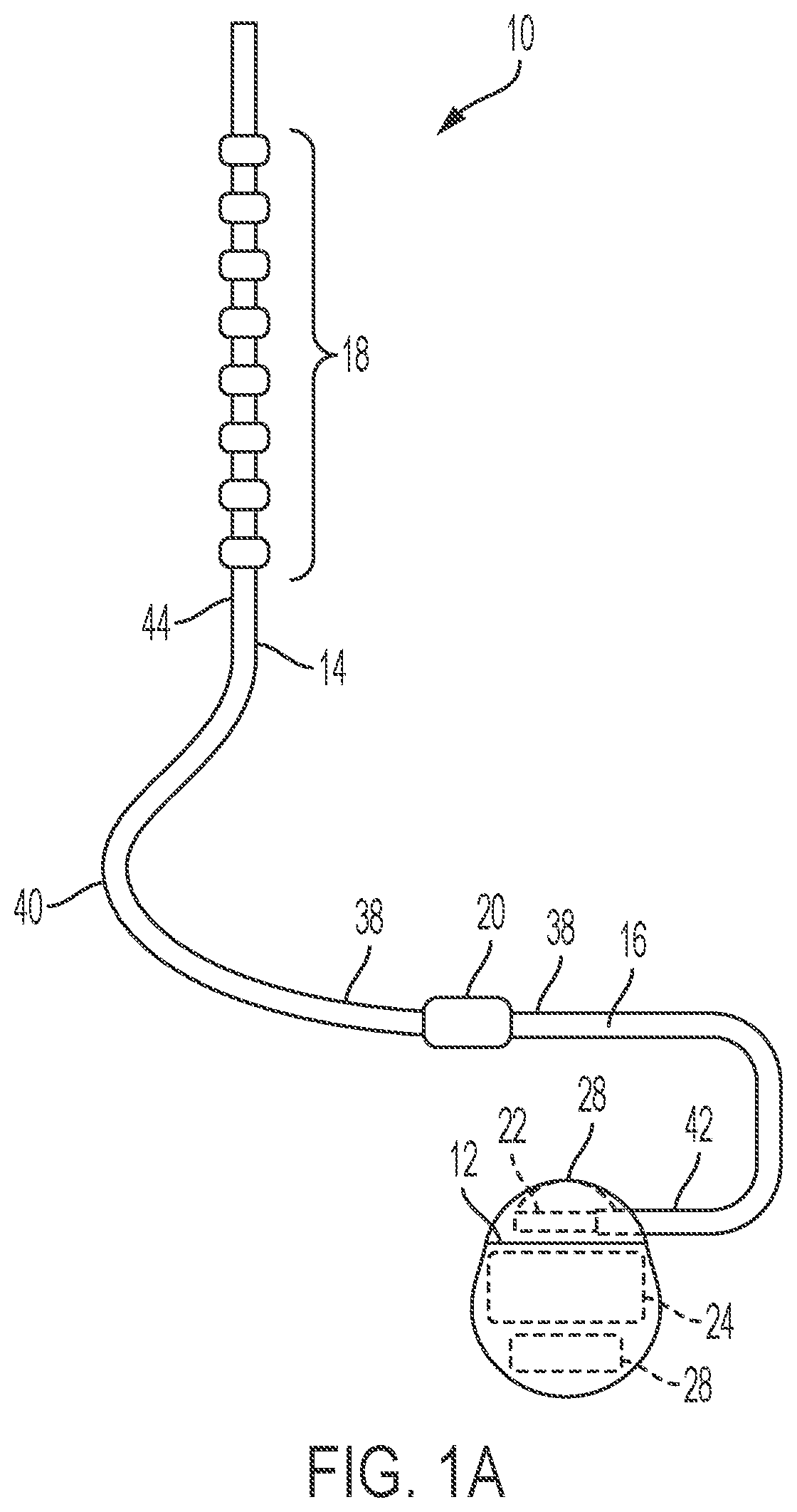
[0019]Bulkhead anchor configurations are provided according to embodiments of the invention for use in anchoring or otherwise discouraging movement of medical device leads. For example, a bulkhead anchor may be utilized with respect to a lead in the form of a catheter comprising part of an implantable medical device operable to deliver an infusate to a targeted tissue or treatment area. As another example, a bulkhead anchor may be utilized with respect to a lead in the form of an electrical lead comprising part of an implantable medical device operable to deliver electrical pulses or signals to a targeted tissue or nerves.

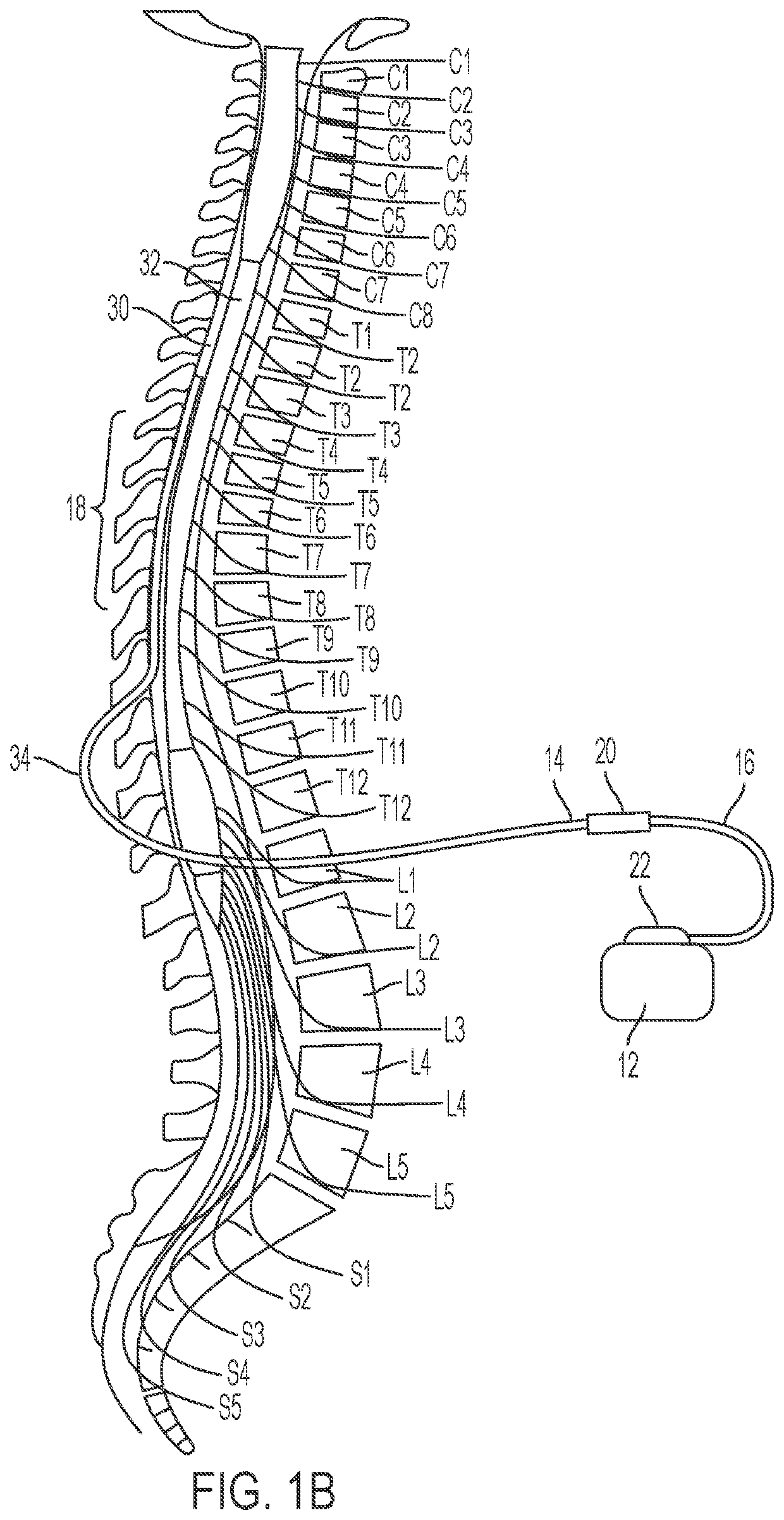
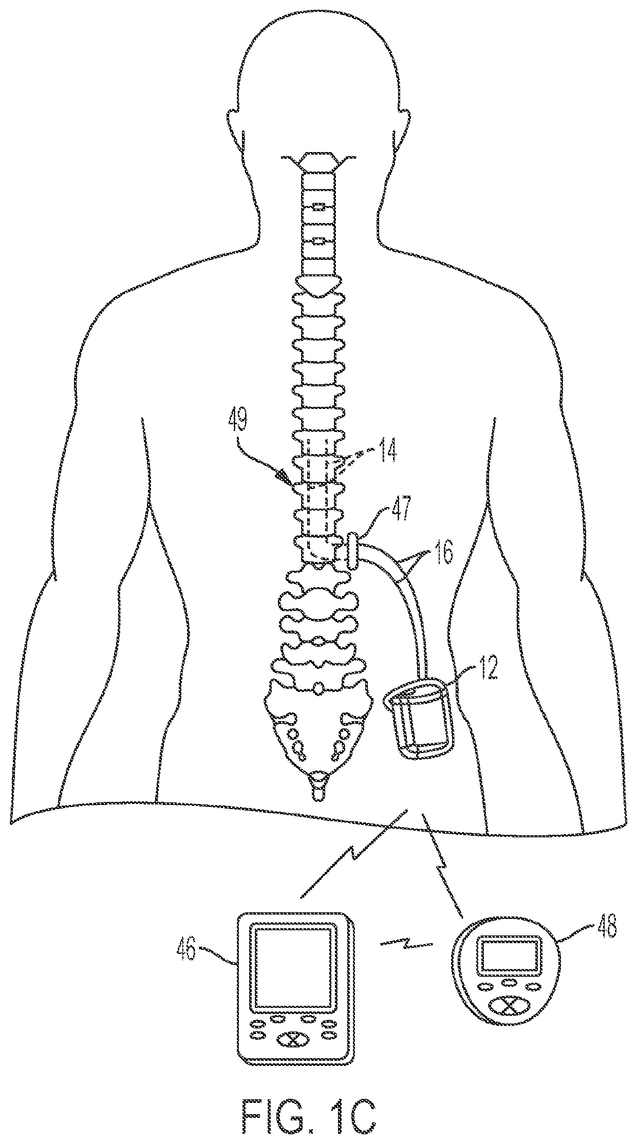
[0020]To aid in understanding concepts herein, the description that follows describes examples relating to implantable medical devices of a spinal cord stimulation (SCS) system. However, it is to be understood that, while embodiments of a bulkhead anchor are well suited for applications in SCS, the disclosure in its broadest aspects may not be so limited. Rather, t...


PUM


Abstract

Systems and methods which provide a bulkhead anchor configuration in which an anchor body includes flexure finger members and a radial bulkhead operable in cooperation to impart a radial compressive force to a corresponding lead body are described. A first portion of a bulkhead anchor body may comprise a plurality of flexure finger members disposed in a corolla configuration forming an anchor lumen through which a lead body may be inserted. A second portion of the bulkhead anchor body may comprise a radial bulkhead having a flexure profile configured to operatively engage the flexure finger members. A locking mechanism may be used to retain the first and second portions of the bulkhead anchor in their relative positions such that the radial compressive force is maintained upon the lead body indefinitely.

Description

CROSS-REFERENCE TO RELATED APPLICATIONS[0001]The present application claims the benefit of U.S. Provisional Patent Application No. 63 / 117,771, entitled “BULKHEAD ANCHOR FOR MEDICAL DEVICE LEADS,” filed Nov. 24, 2020 the disclosure of which is hereby incorporated by reference herein in its entirety as if fully set forth below and for all applicable purposes.TECHNICAL FIELD[0002]The present invention relates to medical device leads and, more particularly, to anchors for leads used in the medical field.BACKGROUND OF THE INVENTION[0003]Implantable medical devices are used for a wide variety of medical conditions. For example, a number of implantable medical devices have been commercially distributed that allow various medical agents to be controllably infused after implantation of the respective device within a patient. Such implantable medical devices may be used for the infusion of insulin, opiates, antispasmodic drugs, intrahepatic chemotherapy agents, and other therapeutic agents in...

Claims


Application Information

Patent Timeline
Patent Type & Authority Applications(United States)
IPC IPC(8): A61N1/375A61N1/05
CPCA61N1/37518A61N1/0558A61N1/057A61N2001/0582
Inventor DAWSON, CHRISJACKSON, ADAMRAINES, AARONREARDON, MANASI
Owner ADVANCED NEUROMODULATION SYST INC
Why Eureka
Try Eureka