Diaphragm coupling tools

a diaphragm and tool technology, applied in the direction of yielding couplings, clamps, couplings, etc., can solve the problems of difficult installation of flexible driveshafts, and achieve the effect of reducing or eliminating damage to flexible driveshafts

Active Publication Date: 2022-03-01
THE BF GOODRICH CO
View PDF22 Cites 0 Cited by
  • Summary
  • Abstract
  • Description
  • Claims
  • Application Information

AI Technical Summary

Benefits of technology

[0005]Each shaft engaging feature can include a u-shaped cut out between two respective tines of the respective first or second plate. Each u-shaped cut out can define a u-shaped edge of the plate that is itself contoured wrapping around the u-shaped edge to provide an interface for a secure fit between the plates and a flexible driveshaft to reduce or eliminate damage to a flexible drive shaft interfacing with the shaft engaging features.

Problems solved by technology

Installation of flexible driveshafts can also be difficult due to support structure and mating part locations, e.g., in fixed-wing and rotary-wing aircraft applications.

Method used


Image

  • Diaphragm coupling tools
  • Diaphragm coupling tools
  • Diaphragm coupling tools

Examples


Embodiment Construction

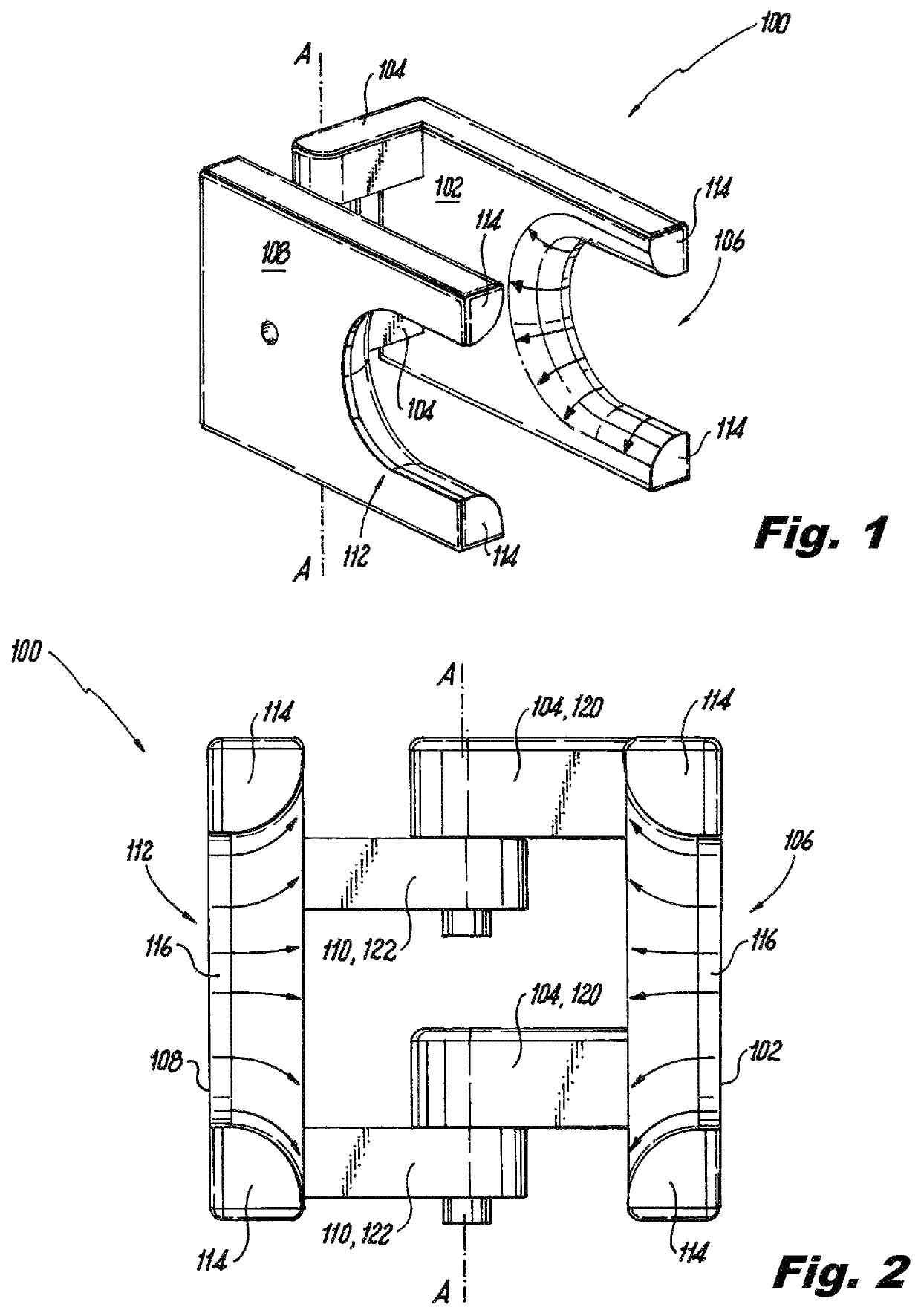
[0017]Reference will now be made to the drawings wherein like reference numerals identify similar structural features or aspects of the subject disclosure. For purposes of explanation and illustration, and not limitation, a partial view of an exemplary embodiment of a tool in accordance with the disclosure is shown in FIG. 1 and is designated generally by reference character 100. Other embodiments of tools in accordance with the disclosure, or aspects thereof, are provided in FIGS. 2-5, as will be described. The systems and methods described herein can be used to facilitate installation and removal of flexible driveshafts such as in fixed-wing and rotary wing aircraft applications.

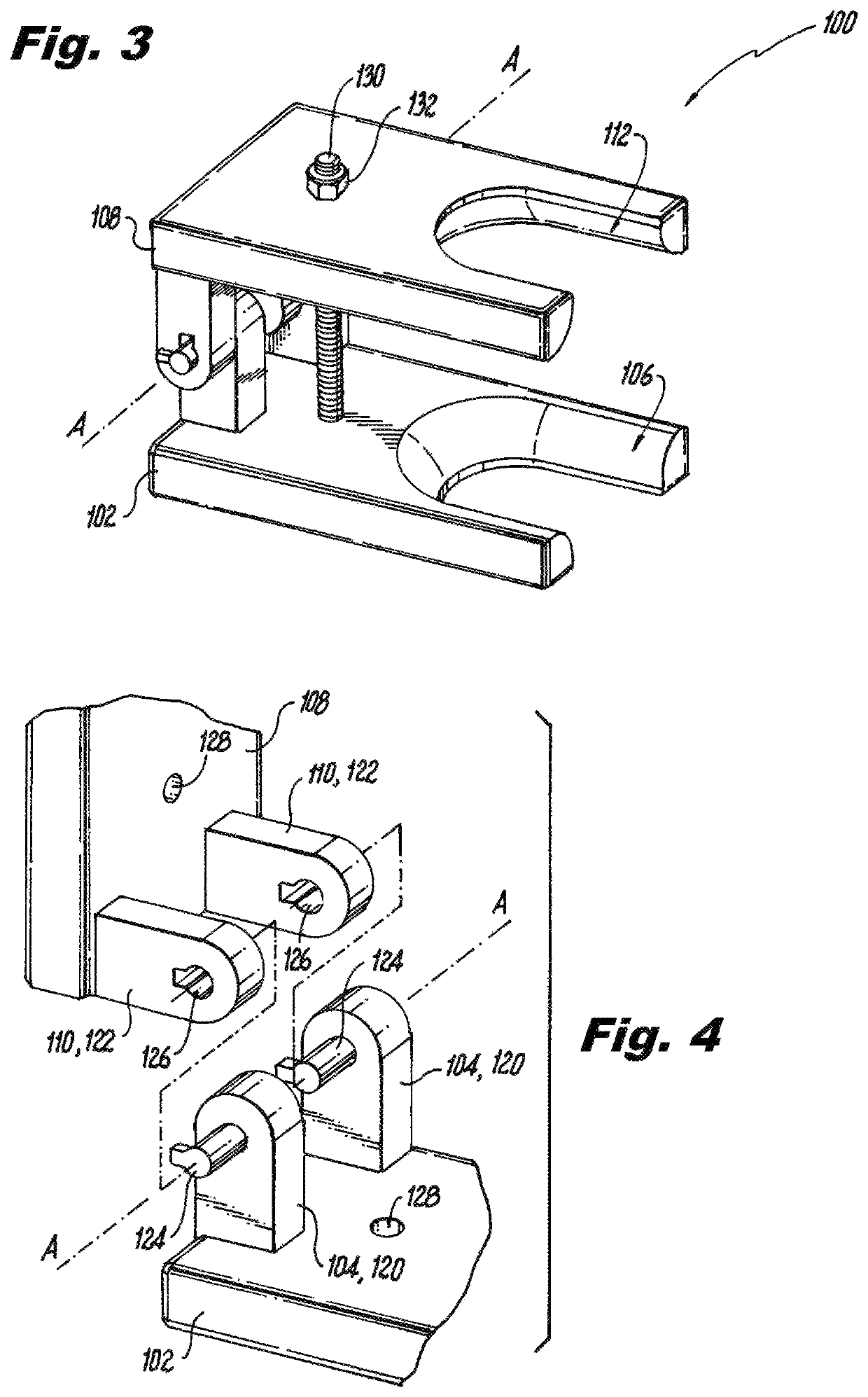
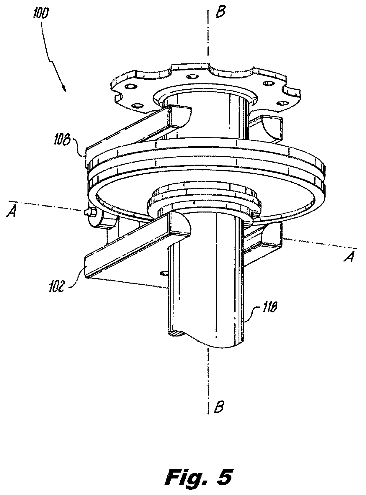
[0018]The tool 100 includes a first plate 102 having a hinge member 104 rigidly extending from the first plate 102. A shaft engaging feature 106 is defined in the first plate 102 opposite the hinge member 104 thereof. A second plate 108 has a hinge member 110 (see also in FIG. 2) rigidly extending from the...


PUM


Abstract

A tool for installation and removal of flexible couplings includes a first plate having a hinge member rigidly extending from the first plate and a shaft engaging feature defined in the first plate opposite the hinge member thereof. A second plate has a hinge member rigidly extending from the second plate and a shaft engaging feature defined in the second plate opposite the hinge member thereof. The hinge members of first and second plates are hinged together for rotation of the first and second plates about a hinge axis to actuate the shaft engaging features toward and away from one another.

Description

BACKGROUND OF THE INVENTION1. Field of the Invention[0001]The present disclosure relates to flexible couplings, and more particularly to tools for manipulating flexible driveshafts.2. Description of Related Art[0002]Flexible couplings are commonly used to transmit torque while accommodating axial and / or angular misalignment between driving and driven shaft components along a load path. The flexible couplings generally have stiffness that opposes the angular misalignment accommodated by the flexible coupling. In some flexible couplings, such as flexible couplings with relatively low spring rates, it can be possible to overstress the flexible coupling, either during installation or removal of the flexible coupling. Installation of flexible driveshafts can also be difficult due to support structure and mating part locations, e.g., in fixed-wing and rotary-wing aircraft applications.[0003]The conventional techniques have been considered satisfactory for their intended purpose. However, ...

Claims


Application Information

Patent Timeline
Patent Type & Authority Patents(United States)
IPC IPC(8): B25B27/14B25B5/04B25B5/10B25B27/28B25B5/14F16D3/72
CPCB25B27/14B25B5/04B25B5/103B25B5/14B25B27/28F16D3/72F16D2250/0084
Inventor REED, BRAYTON PAUL
Owner THE BF GOODRICH CO
Why Eureka
Try Eureka