Posterior pedicle screw and plate system and methods

Active Publication Date: 2009-10-27
WARSAW ORTHOPEDIC INC
View PDF88 Cites 36 Cited by
  • Summary
  • Abstract
  • Description
  • Claims
  • Application Information

AI Technical Summary

Benefits of technology

[0014]In yet another embodiment, a method is provided comprising providing a plate member having a curvature approximating a natural spinal lordosis curvature, a first slot and a second slot with a sloped surface formed within said second slot, and sized to be inserted into the body through a minimally-invasive, open or other surgical opening: inserting the plate member through the opening into a patient proximate to a vertebra to which the plate member is intended to be attached; placing a first anchoring member through the first slot and into a first vertebra; placing a second anchoring member through the second slot and into a second vertebra; a

Problems solved by technology

Such features enable bone anchors to be placed at angles which are optimal for anchoring, thus reducing the chance of loosening, pull-out, or other movement of the anchors while not compromising the optimal positioning of the fixation plate.
The compression fit of the bolt and collar within the plate can present difficulty in assembling the apparatus, particularly in a fluid-prevalent environment.
Further, since the washers in that system lie outside of the elongated member, they increase the thickness of the overall construct, with the attendant increase in the difficulty of use in a small surgical space and in the potential for patient discomfort.
Even with that method, however, additional tools such as a rod reducer are required.
For example, to compress (i.e., push together) or distract (i.e., push apart) two vertebrae, it is known to use, among other relatively large tool

Method used


Image

  • Posterior pedicle screw and plate system and methods
  • Posterior pedicle screw and plate system and methods
  • Posterior pedicle screw and plate system and methods

Examples


Embodiment Construction

[0022]For the purposes of promoting an understanding of the principles of the invention, reference will now be made to the embodiments illustrated herein and specific language will be used to describe the same. It will nevertheless be understood that no limitation of the scope of the invention is thereby intended. Any alterations and further modifications in the described processes, systems or devices, and any further applications of the principles of the invention as described herein, are contemplated as would normally occur to one skilled in the art to which the invention relates.

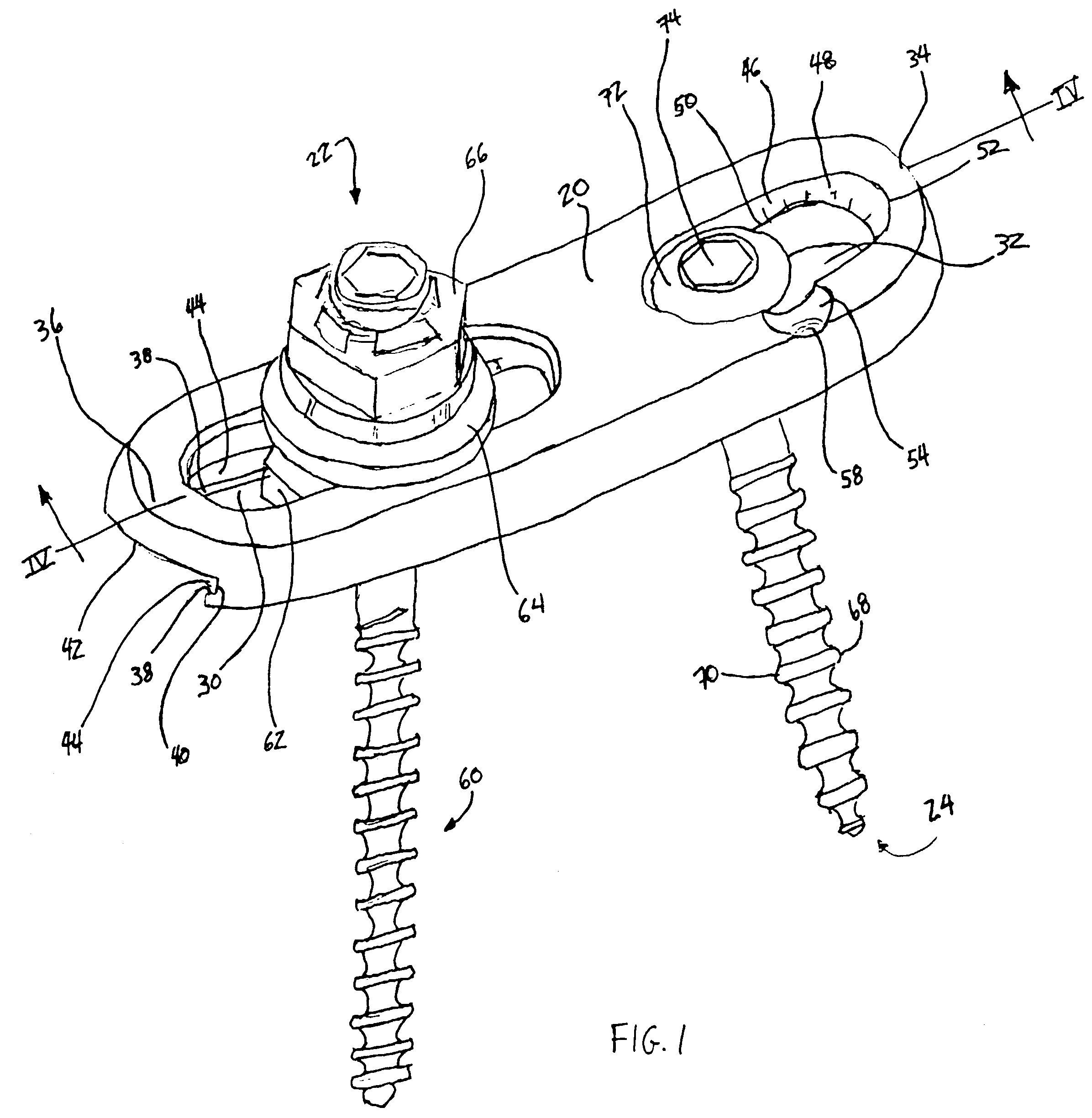
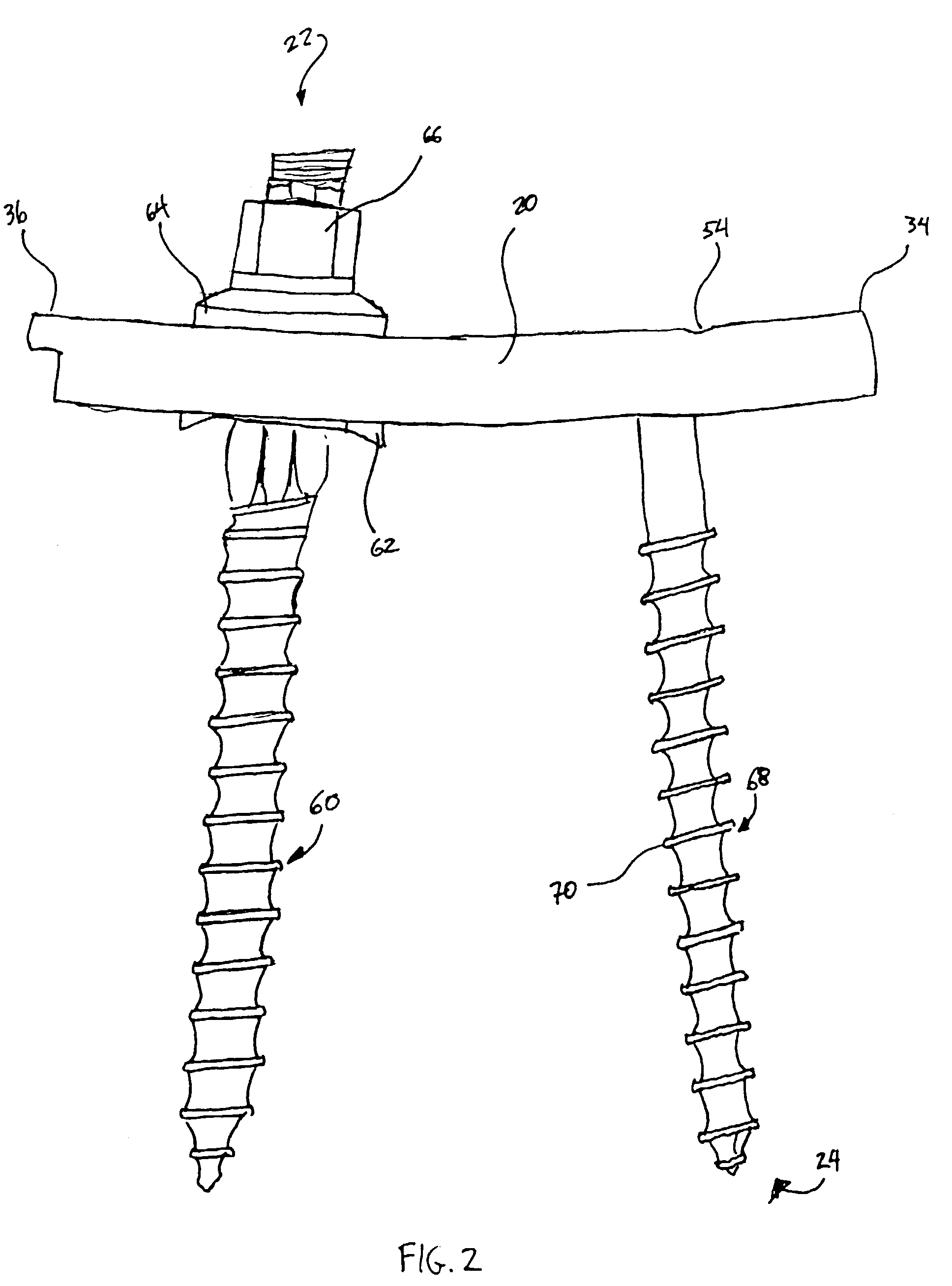
[0023]Referring now generally to FIGS. 1-5, there is shown a plate member 20 with a multi-axial bone fixation member 22 and a bone fixation member 24. Plate member 20 is elongated and includes a plurality of slots. In the illustrated embodiment, plate member 20 includes two slots 30 and 32, although it will be appreciated additional slots could be placed in plate member 20. In a particular embodiment, pla...


PUM


Abstract

An apparatus is provided for correcting spinal abnormalities, and particularly for providing compression and/or distraction of vertebrae without additional tools or instrumentation. A plate member is provided with a plurality of slots, one of which has a sloped internal edge or surface. The plate is anchored to one vertebra by a first anchor, and a second anchor is then placed through the slot with the sloped internal edge or surface and tightened. Such tightening causes the plate to move with respect to the tightened anchor, and thus to transmit compression or distraction to the vertebrae. The apparatus is particularly useful in minimally-invasive surgeries but can also be used in more traditional open surgeries.

Description

FIELD OF THE INVENTION[0001]The present invention relates to an orthopedic implant assembly for use in stabilizing bone members in a desired spatial relationship in correcting bone misalignment disorders or for spinal or other bone fusion. In particular, the invention concerns a multi-axial spinal fixation system incorporating an elongated member such as a plate.BACKGROUND OF THE INVENTION[0002]In the art of orthopedic surgery, and particularly in spinal surgery, it has long been known to affix an elongated member, such as a plate or rod, to bones in order to hold them and support them in a given position. For example, in a procedure to fuse damaged, diseased, malformed, or otherwise abnormal vertebrae, the vertebrae are positioned in a corrected position by a surgeon. An elongated plate is placed adjacent to the vertebral bone, and bone anchors, such as specially-configured screws or bolts, are employed to secure the plate to the bones. With such anchors, placement is accomplished ...

Claims


Application Information

Patent Timeline
IPC IPC(8): A61B17/70A61B17/80
CPCA61B17/7007A61B17/701A61B17/7059A61B17/8047A61B17/8014A61B17/8042
Inventor FOLEY, KEVIN T.BRUNEAU, AUREMELKENT, ANTHONY J.ROEHM, III, THOMAS E.
Owner WARSAW ORTHOPEDIC INC
Why Eureka
Try Eureka