
System and method for releasably holding a surgical instrument

Inactive Publication Date: 2005-12-22
SRI INTERNATIONAL
View PDF99 Cites 29 Cited by
  • Summary
  • Abstract
  • Description
  • Claims
  • Application Information

AI Technical Summary

Benefits of technology

[0010] According to the invention, a system and method provide for releasably holding a surgical instrument during conventional open surgery or endoscopic procedures, such as laparoscopy. The instrument comprises an elongate shaft with proximal and distal ends and a mounting means having a protrusion extending radially from the shaft between the proximal and distal ends. An instrument holder comprises a support having a body with an axial passage for receiving the instrument shaft and a first hole in communication with the axial passage for receiving the protrusion. A second hole is cut into the body transversely to and in communication with the first hole so that the protrusion can be rotated within the second hole. To prevent the instrument from being accidently twisted and thereby disengaged from the instrument holder during surgery, the holder further includes a locking means coupled to the body for automatically locking the protrusion within the second hole thereby releasably locking the instrument to the instrument holder.
[0011] In a preferred configuration, the protrusion of the mounting means comprises a pair of opposing arms, such as mounting pins, extending outward from the instrument shaft. The first hole is an axially extending slot for receiving the mounting pins and the second hole is a perpendicular locking slot having a first portion aligned with the axial slot and a second portion extending circumferentially around the body of the instrument support. With this configuration, the mounting pins can be slid through the axial slot and rotated into the locking slot to attach the instrument to the holder. The instrument can be removed by performing the same two steps in reverse order. With this twist-lock motion, the surgeon can rapidly engage and disengage various instruments from the instrument holder during a surgical procedure.

Problems solved by technology

One such challenge is that different surgical instruments will be attached and detached from the same instrument holder a number of times during an operation.
In laparoscopic procedures, for example, the number of entry ports into the patient's abdomen is generally limited during the operation because of space constraints as well as a desire to avoid unnecessary incisions in the patient.
Likewise, in open surgery, there is typically not enough room around the surgical site to position more than one or two surgical manipulators, and so the surgeon's assistant will be compelled to frequently remove instruments from the holder and exchange them with other surgical tools.

Method used


Image

  • System and method for releasably holding a surgical instrument
  • System and method for releasably holding a surgical instrument
  • System and method for releasably holding a surgical instrument

Examples


Embodiment Construction

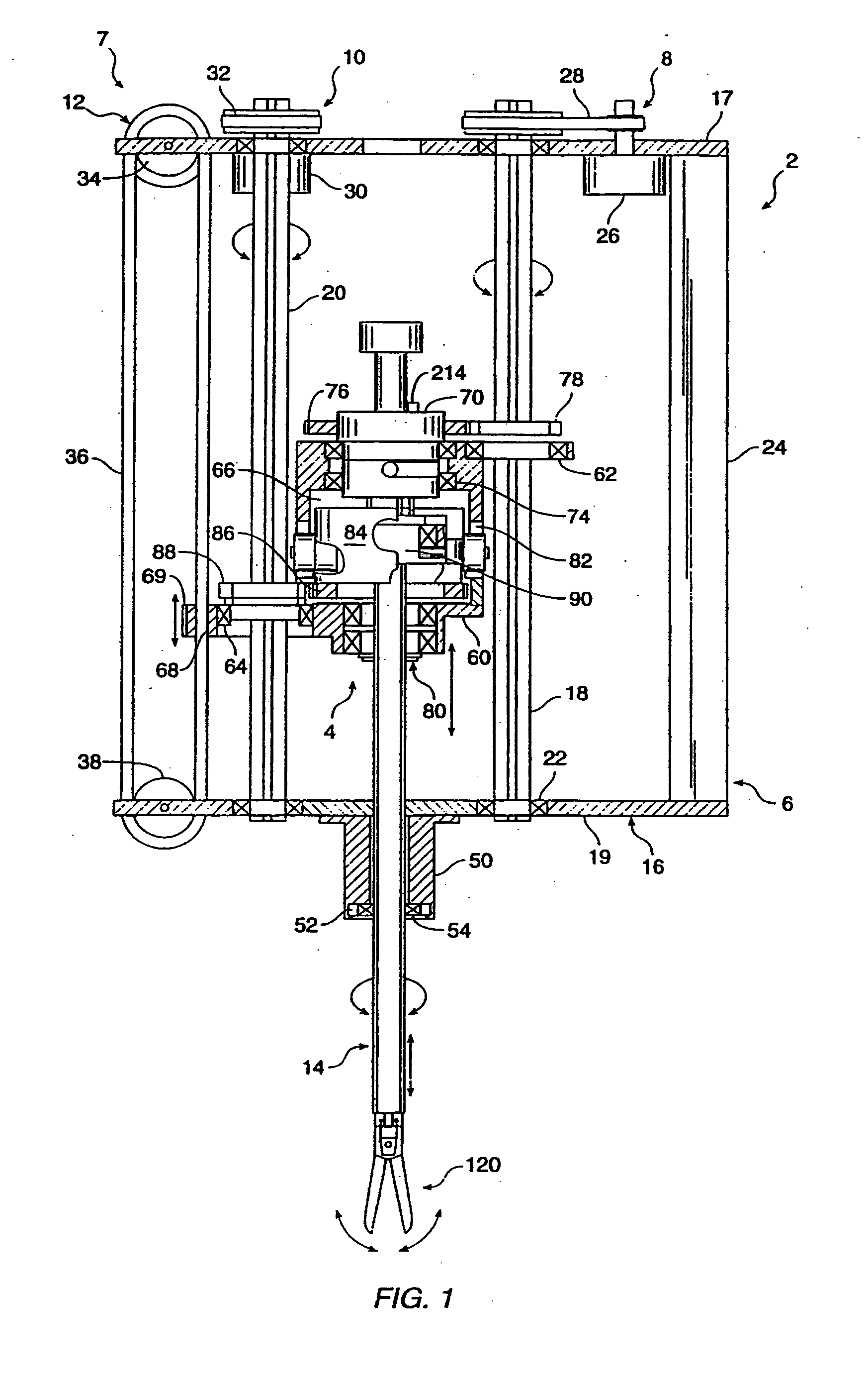
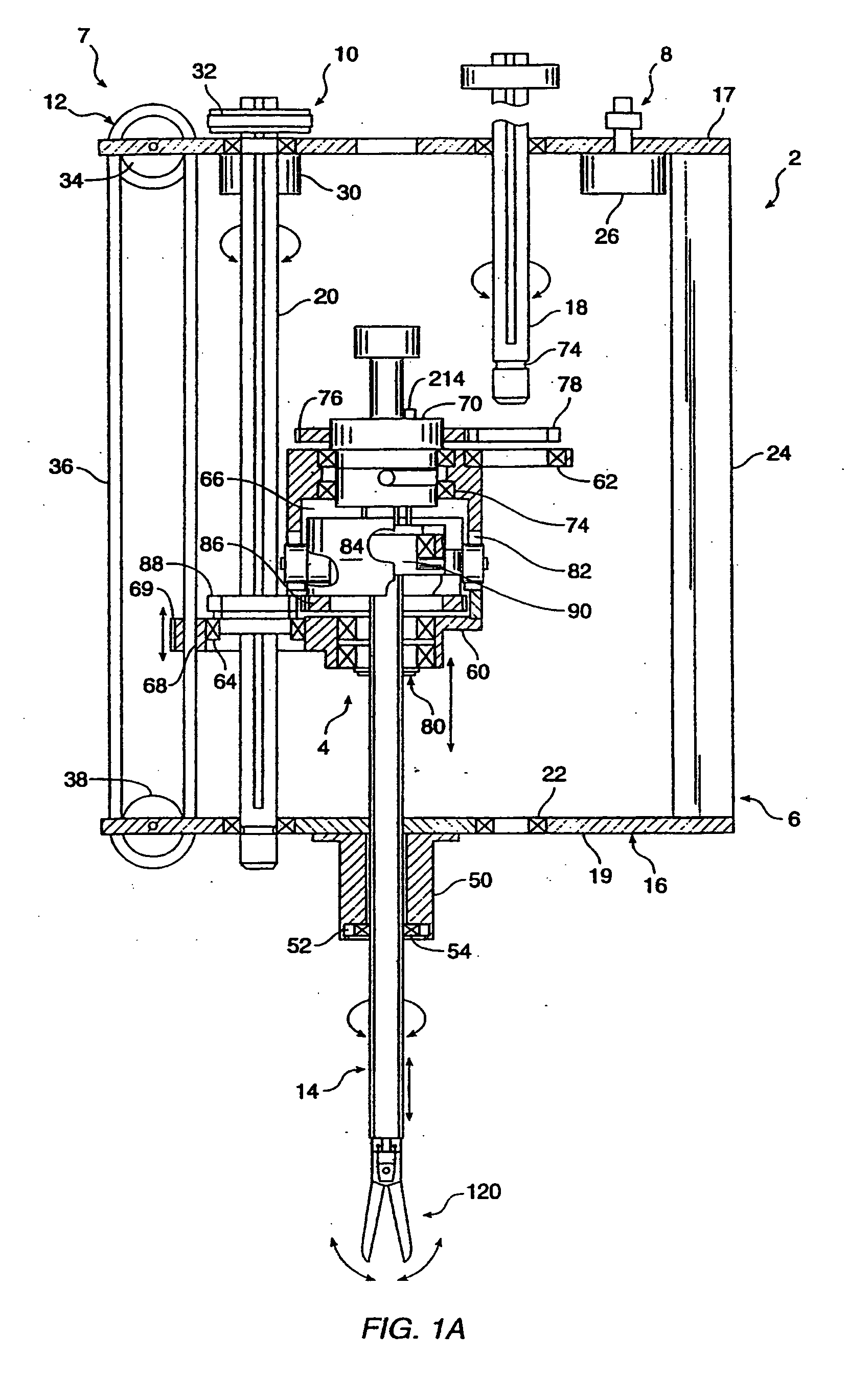
[0026] Referring to the drawings in detail, wherein like numerals indicate like elements, a manipulator assembly 2 is illustrated according to the principles of the invention. Manipulator assembly 2 generally includes an instrument holder 4 removably mounted to a base 6 and a drive assembly 7 for manipulating a surgical instrument 14 releasably coupled to instrument holder 4.

[0027] Referring to FIG. 1, base 6 comprises a frame 16 having proximal and distal elongate support members 17, 19 and first and second ball-spline shafts 18, 20 rotatably coupled to support members 17, 19 via bearings 22. Frame 16 further includes a support bracket 24 for attaching manipulator assembly 2 to a remote center positioner 300, as discussed in more detail below (see FIG. 9). Drive assembly 7 comprises first, second and third drives 8, 10, 12, which are mounted to frame 16 and configured to provide three degrees of freedom to surgical instrument 14. In the preferred embodiment, first drive 8 rotates ...


PUM


Abstract

The invention is directed to a system and method for releasably holding a surgical instrument (14), such as an endoscopic instrument configured for delivery through a small percutaneous penetration in a patient. The instrument comprises an elongate shaft (100) with a pair of mounting pins (116) laterally extending from the shaft between its proximal and distal ends. An instrument holder comprises a support having a central bore (202) and an axially extending slot (204) for receiving the instrument shaft and the mounting pins. A pair of locking slots (206) are cut into the support transversely to and in communication with the axial slot so that the mounting pins can be rotated within the locking slots. The instrument support further includes a latch assembly for automatically locking the mounting pins within the locking slots to releasably couple the instrument to the instrument holder. With this twist-lock motion, the surgeon can rapidly engage and disengage various instruments from the holder during a surgical procedure, such as open surgery, laparoscopy or thoracoscopy.

Description

CROSS-REFERENCES TO RELATED APPLICATIONS [0001] This application is a continuation of U.S. application Ser. No. 10 / 265,285 filed Oct. 4, 2002, which is a continuation of U.S. application Ser. No. 09 / 521,253 filed on Mar. 8, 2000, now U.S. Pat. No. 6,461,372, which is a continuation of U.S. application Ser. No. 09 / 105,706 filed on Jun. 26, 1998, now U.S. Pat. No. 6,080,181, which is a division of U.S. application Ser. No. 08 / 848,934, filed on May 1, 1997, now U.S. Pat. No. 5,810,880, which is a division of application Ser. No. 08 / 485,587, filed on Jun. 7, 1995, now U.S. Pat. No. 5,649,956, all of which are incorporated herein by reference.STATEMENT AS TO RIGHTS TO INVENTIONS MADE UNDER FEDERALLY SPONSORED RESEARCH OR DEVELOPMENT [0002] This invention was made with Government support under contract awarded by the National Institute for Health (NIH) under grant number 5 R01GM-44902-02. The Government has certain rights in this invention.REFERENCE TO A “SEQUENCE LISTING,” A TABLE, OR A ...

Claims


Application Information

Patent Timeline
IPC IPC(8): A61B17/00A61B17/28A61B19/00B25J9/10B25J15/04B25J18/04
CPCA61B17/29Y10T403/581A61B2017/00464A61B2017/2932A61B2019/223A61B2019/2234A61B2019/2242A61B2019/2292A61B2019/265B25J9/1065B25J15/04B25J18/04A61B2017/00477Y10T403/587A61B19/22A61B2090/506A61B34/70A61B34/71A61B34/35A61B2034/305A61B34/76F16B2200/69F16B2200/71
Inventor JENSEN, JOEL F.GREEN, PHILIP S.
Owner SRI INTERNATIONAL
Learn More