

Phosphor and including the same, light emitting apparatus, illuminating apparatus and image display
a technology of phosphor and light emitting device, applied in the field of high-efficiency light emitting device, can solve the problems of not being realized and no phosphor having high emission efficiency has been developed under the present situation, and achieves high luminance, high color rendering properties, and efficient emission of visible ligh
- Summary
- Abstract
- Description
- Claims
- Application Information
AI Technical Summary
Benefits of technology
Problems solved by technology
Method used
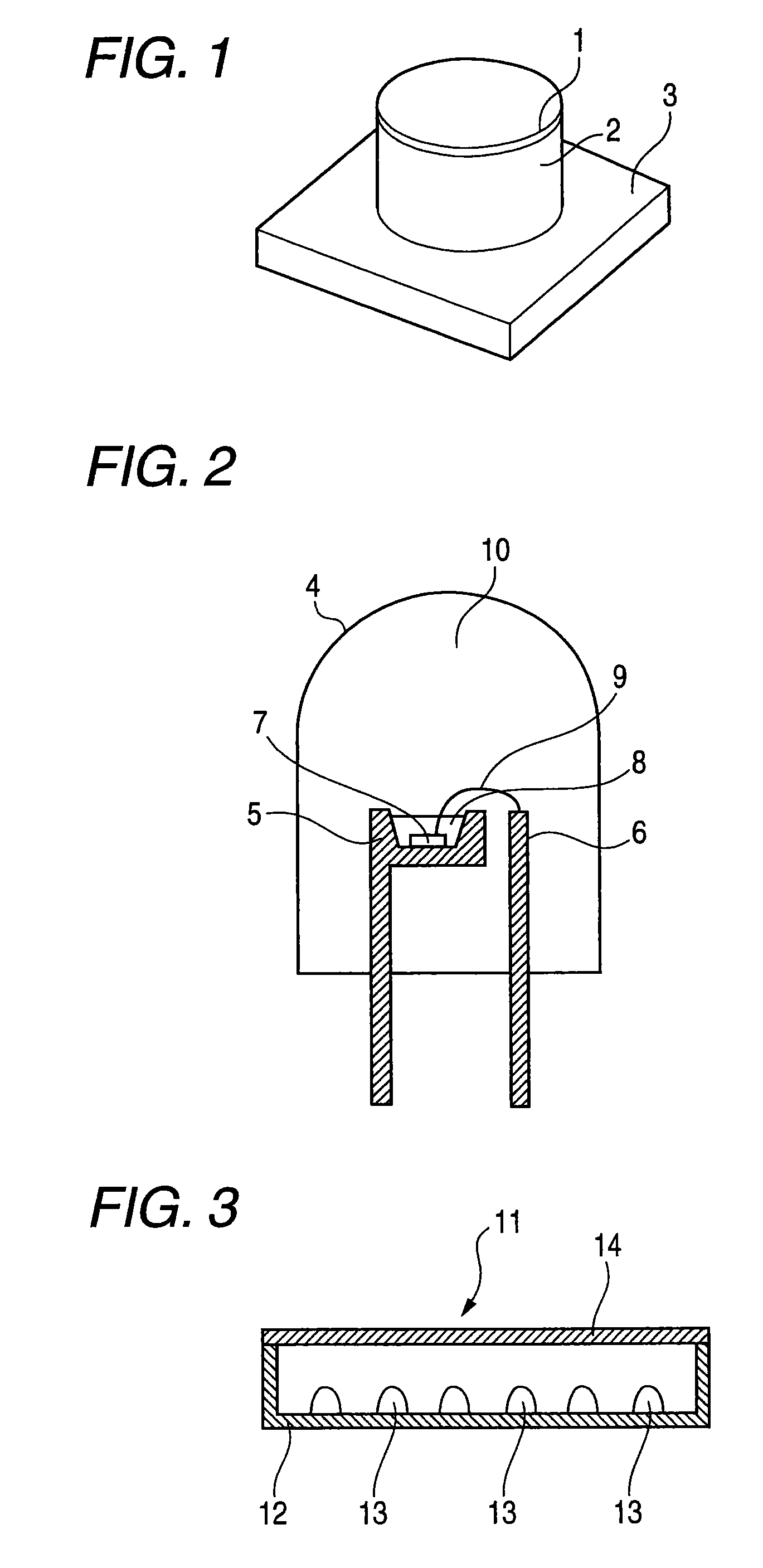
Image

Examples
examples
[0118]The present invention will be illustrated with reference to examples in more detail below, but the present invention should not be construed as being limited to the following examples within its gist.
example a-1
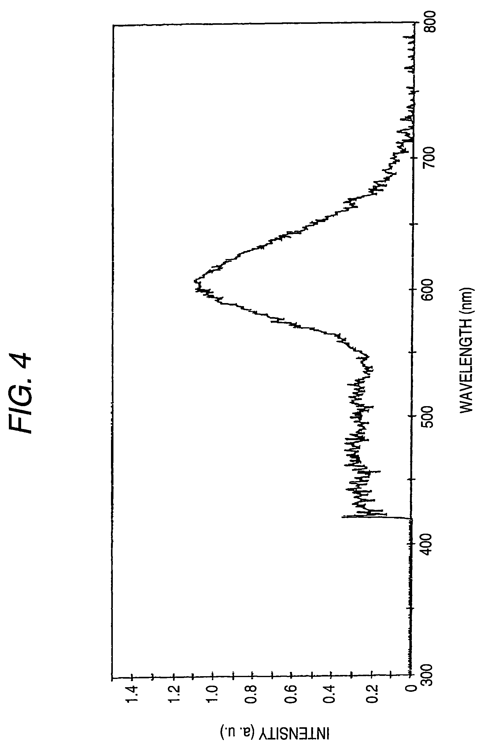
[0119]An aqueous solution of Ba(NO3)2, an aqueous solution of Ca(NO3)2.4H2O, an aqueous solution of Eu(NO3)3.6H2O, an aqueous solution of Mn(NO3)2.6H2O and a suspension of colloidal silica (Sio2) (the molar ratio of Ba(NO3)2, Ca(NO3)2.4H2O, Eu(NO3)3.6H2O, Mn(NO3)2.6H2O and SiO2 is 0.64:0.96:0.2:0.2:1) were mixed in a platinum container and dried. Then, the mixture was burnt by heating under a stream of nitrogen gas containing 4% of hydrogen at 1050° C. for 2 hours to produce a phosphor Ba0.64Ca0.96Eu0.2Mn0.2SiO4 (phosphor used in a second light emitter). An emission spectrum at the time when this phosphor was excited at 400 nm, a main wavelength in an ultraviolet light region of a GaN-based light emitting diode, was measured. The wavelength of an emission peak thereof, the intensity of the emission peak at the time when the intensity of an emission peak of Comparative Example A-2 described later is taken as 100 (hereinafter referred to as the relative intensity), and the half-value ...
example a-2
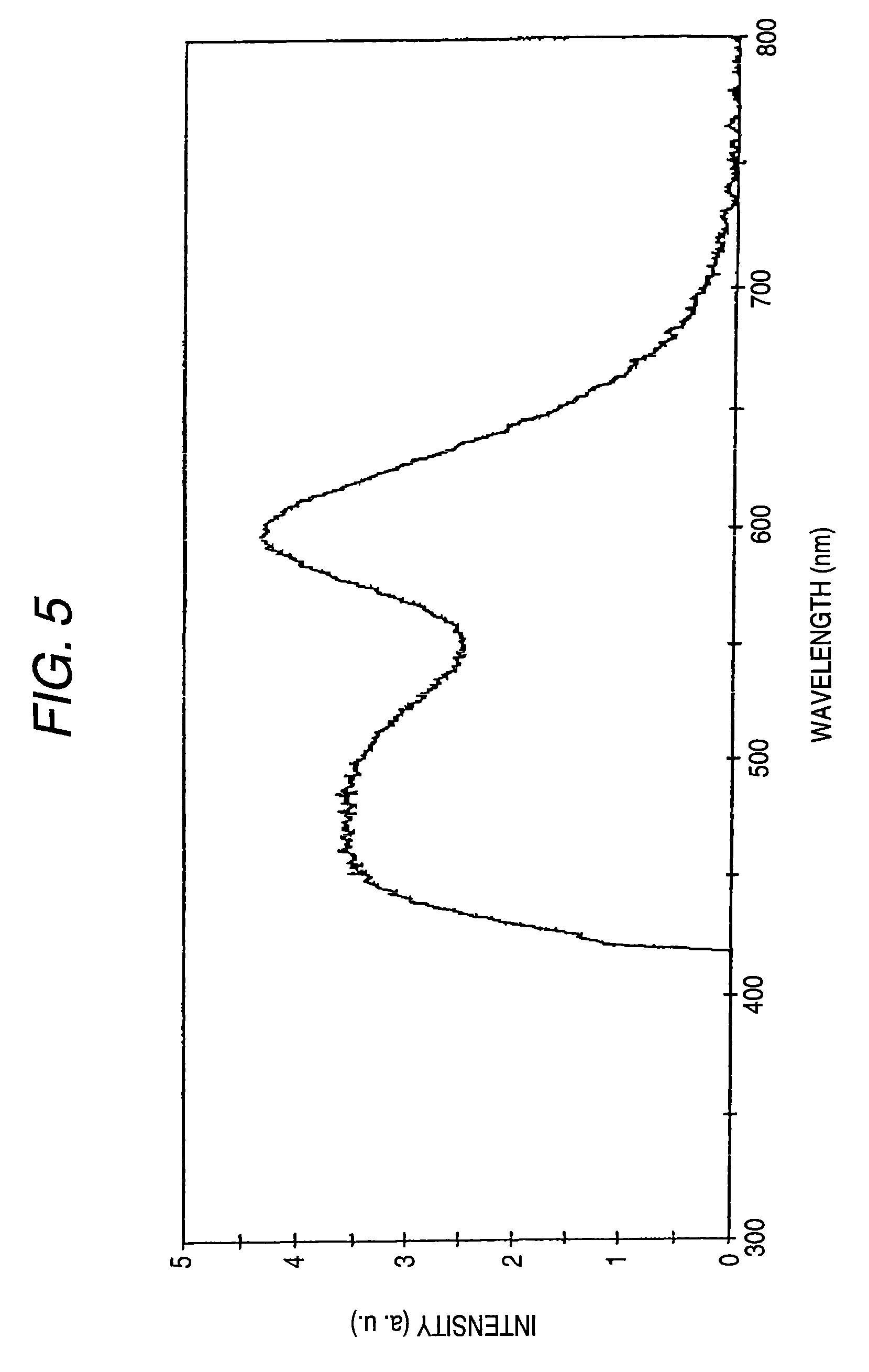
[0123]A phosphor Ba0.84Ca0.56Eu0.3Mn0.3SiO4 was produced in the same manner as in Example A-1 with the exception that an aqueous solution of Ba(NO3)2, an aqueous solution of Ca(NO3)2.4H2O, an aqueous solution of Eu(NO3)3.6H2O, an aqueous solution of Mn(NO3)2.6H2O and a suspension of colloidal silica (SiO2) (the molar ratio of Ba(NO3)2, Ca(NO3)2.4H2O, Eu(NO3)3.6H2O, Mn(NO3)2.6H2O and SiO2 is 0.84:0.56:0.3:0.3:1) were used as original solutions. An emission spectrum at the time when this phosphor was excited at 400 nm, a main wavelength in an ultraviolet light region of a GaN-based light emitting diode, was measured. The wavelength, relative intensity and half-value width of an emission peak thereof are shown in Table 1. This phosphor has a sufficiently wide half-value width, gives good color rendering properties, and emits a light red color having a peak wavelength within the range of 590 nm to 620 nm. This reveals that this phosphor emits reddish light which feels bright.
PUM
| Property | Measurement | Unit |
|---|---|---|
| molar ratio | aaaaa | aaaaa |
| mol % | aaaaa | aaaaa |
| molar ratio | aaaaa | aaaaa |
Abstract
Description
Claims
Application Information