Method and circuit for controlling an LED

a technology of leds and circuits, applied in the direction of electric variable regulation, process and machine control, instruments, etc., can solve the problems of cfls broken mercury presenting a health hazard if not promptly and properly cleaned, and emitting ligh

Inactive Publication Date: 2009-10-27
MDL CORP
View PDF6 Cites 51 Cited by
  • Summary
  • Abstract
  • Description
  • Claims
  • Application Information

AI Technical Summary

Benefits of technology

[0010]FIG. 1 is a schematic block diagram of an LED dimmer control circuit in accordance with a preferred embodiment of the present invention; and
[0011]FIG. 2 is an...

Problems solved by technology

However, CFLs contain a small amount of mercury (Hg), which makes disposal rather difficult since the bulbs cannot simply be thrown in the garbage.
Additionally, the mercury from broken CFLs can present a health hazard if not promptly and properly cleaned up.
One disadvantage of LEDs results from the nature of the diode, that is, the LED will only emit light when c...

Method used


Image

  • Method and circuit for controlling an LED
  • Method and circuit for controlling an LED
  • Method and circuit for controlling an LED

Examples


Embodiment Construction

[0012]Certain terminology is used in the following description for convenience only and is not limiting. The words “right”, “left”, “lower”, and “upper” designate directions in the drawings to which reference is made. The words “inwardly” and “outwardly” refer to directions toward and away from, respectively, the geometric center of the device and designated parts thereof. The terminology includes the above-listed words, derivatives thereof, and words of similar import. Additionally, the words “a” and “an”, as used in the claims and in the corresponding portions of the specification, mean “at least one.”

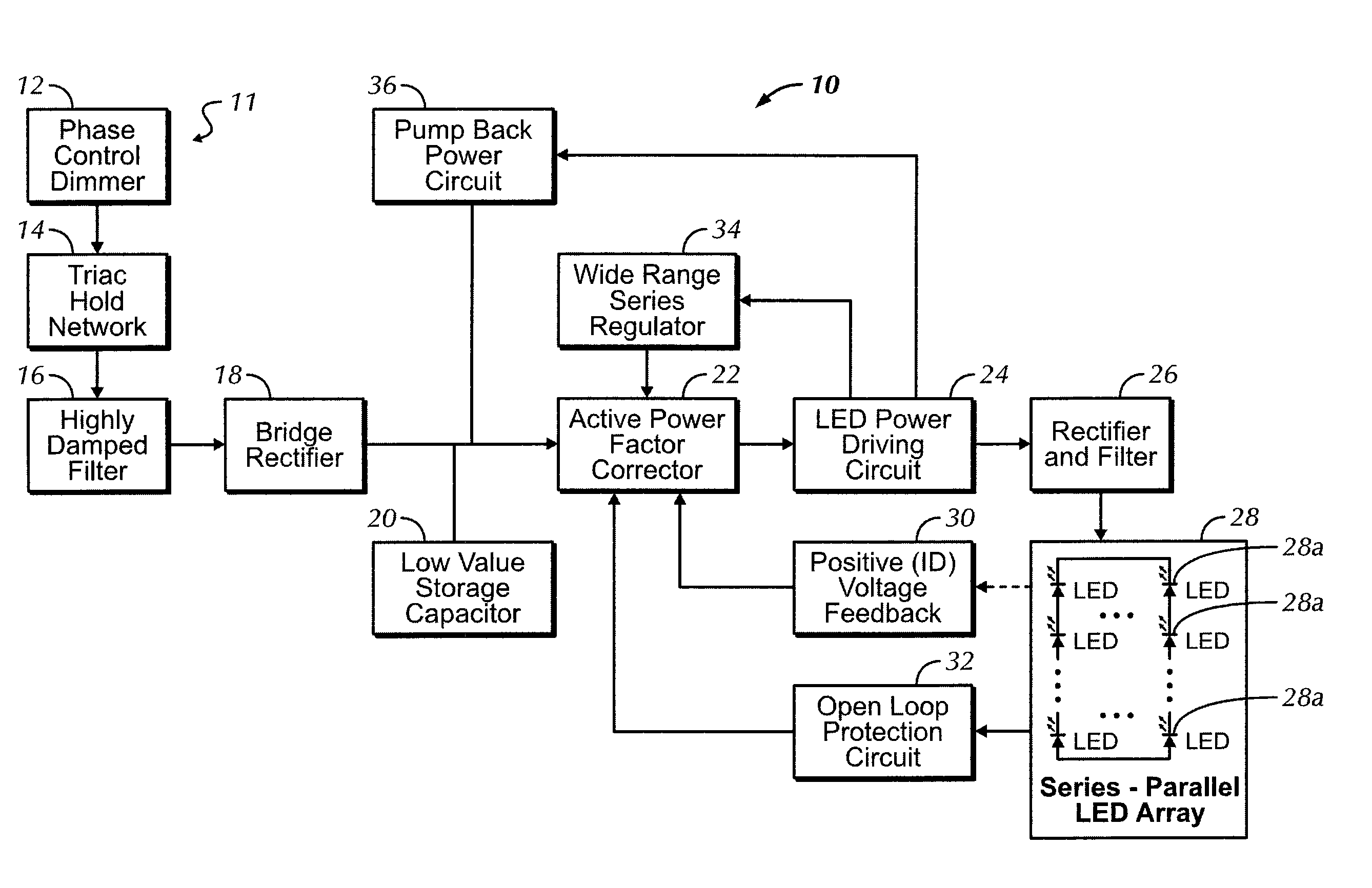
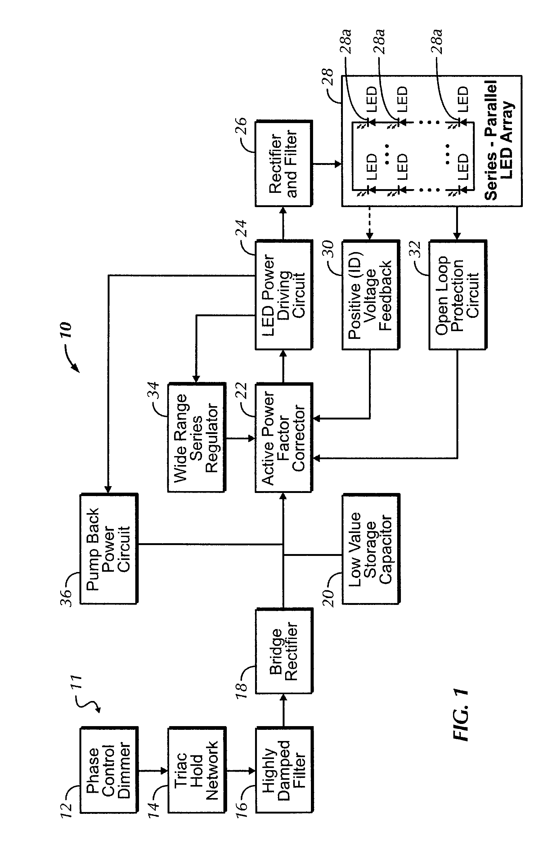
[0013]Referring to the drawings in detail, wherein the same reference numerals indicate like elements throughout, there is shown in FIG. 1 a schematic block diagram of an LED dimmer control circuit 10 in accordance with a preferred embodiment of the present invention. The control circuit 10 is coupled to a dimmer-controlled power line 11. The dimmer-controlled power line 11 preferabl...


PUM


Abstract

A control circuit coupled to a power line controlled by a dimmer having a switching device includes, for example, an active power factor correction circuit receiving power from a bridge rectifier and storage capacitor and drawing an average continuous current when the switching device is “on.” An LED power driving circuit receives a controlled current from the active power factor correction circuit and generates an output current received by at least one LED outputting visible light. A positive voltage feedback circuit senses a feedback voltage across the LED, through the LED power driving circuit, and sends the feedback voltage to the active power factor correction circuit. A pump back power circuit is electrically coupled to the LED power driving circuit and applies a bias voltage to an output of the bridge rectifier to power the active power factor correction circuit when the switching device is “off.”

Description

CROSS REFERENCE TO RELATED APPLICATIONS[0001]The application claims priority to U.S. Provisional Patent Application No. 61 / 059,531, filed Jun. 6, 2008, entitled, “Method and Circuit for Controlling and LED.”BACKGROUND OF THE INVENTION[0002]An embodiment of the present invention relates generally to control circuits for use with standard dimmer switches, and more particularly, to an LED driver circuit for use with standard incandescent phase control dimmers.[0003]With the rising costs of energy, the search continues for lighting solutions that consume less power and operate at a lower cost. Compact fluorescent light (CFL) bulbs were thought to be one energy efficient answer. However, CFLs contain a small amount of mercury (Hg), which makes disposal rather difficult since the bulbs cannot simply be thrown in the garbage. Additionally, the mercury from broken CFLs can present a health hazard if not promptly and properly cleaned up. The Environmental Protection Agency (EPA) has issued g...

Claims


Application Information

Patent Timeline
IPC IPC(8): H05B37/02
CPCH05B33/0893Y02B20/348H05B45/58Y02B20/30
Inventor KOHLER, RAYMOND
Owner MDL CORP
Why Eureka
Try Eureka