
Placido projector for corneal topography system

a topography system and projector technology, applied in the field of corneal topography systems, can solve the problems of patient vision problems, time-consuming process, and the inability to create certain non-circular patterns using machining or molding operations

Inactive Publication Date: 2009-11-03
EYESYS VISION
View PDF5 Cites 29 Cited by
  • Summary
  • Abstract
  • Description
  • Claims
  • Application Information

AI Technical Summary

Problems solved by technology

Variations in the shape of the cornea can result in light not being diffracted into the focal point of the eye thereby producing vision problems for the patient.
While concentric ring images on placido projectors can be produced on a machinist lathe, the production requires a significant investment in tooling and fixtures to hold a uniquely shaped part in a conventional machinist tool, and the process is time intensive.
Also, certain non-circular patterns cannot be created using machining or molding operations.

Method used


Image

  • Placido projector for corneal topography system
  • Placido projector for corneal topography system
  • Placido projector for corneal topography system

Examples


Embodiment Construction

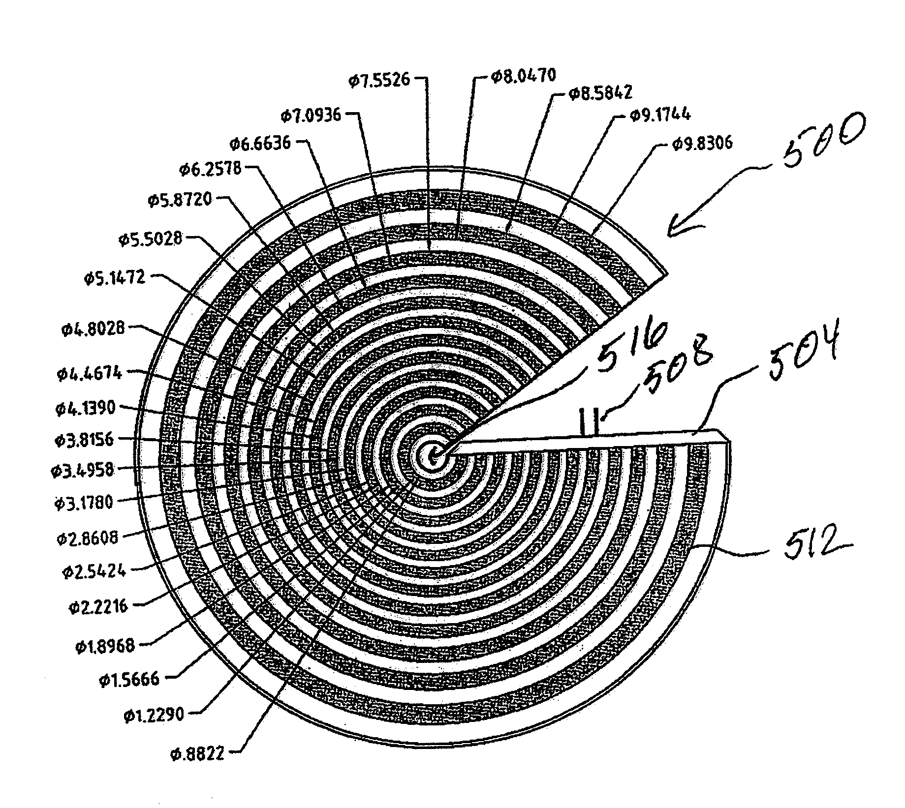
[0020]FIG. 5 illustrates a placido projector 500 in accordance with one embodiment of the invention. The placido projector comprises a substrate 504. The substrate 504 may be made from a flexible material such as polyester. The substrate 504 is embedded with dielectric phosphor. The substrate 504 is coupled to electric conductors 508 so that electric current can be applied to the substrate 504.

[0021]In one embodiment, electric conductors 508 may be printed on the substrate 504 so that the substrate 504 can be electrically excited. When electric current is applied to the substrate 504, the substrate 504 emits light. As will be apparent, the substrate 504 can be an EL panel that emits light when excited with AC current.

[0022]One side of the placido projector 500 is coated with a plurality of concentric opaque rings 512. In one embodiment, silk screening method is used to coat one side of the placido projector 500 with a plurality of opaque concentric rings. Silk screening is also know...


PUM


Abstract

A placido projector for a corneal topography system includes a substrate having dielectric phosphor. The substrate is configured to be activated by electric current and responsive to emit light. A plurality of opaque, concentric rings are formed on the substrate. When the substrate emits light responsive to the electric current, a placido image is projected. The concentric rings can be formed using silk screening or other techniques. The dielectric phosphor can be micro-encapsulated and deposited onto the substrate. The substrate may be an electro-luminance panel. A protective cover is placed adjacent to the substrate to retain the substrate in a predetermined shape. In one embodiment, the placido projector has a frusto conical shape.

Description

FIELD OF THE INVENTION[0001]The present invention relates generally to corneal topography systems. More specifically, the invention relates to a placido projector for a corneal topography system.BACKGROUND OF THE INVENTION[0002]Increased use of surgical techniques to correct vision problems has resulted in an increased need for data relating to the topography of the cornea of the eye. Deformations in the cornea of the eye are mainly responsible for vision problems experienced by patients. The shape of the patient's cornea is a significant factor to such eye diseases such as myopia. An eye with a perfect vision has a near spherical cornea so that incident light is diffracted inward towards a focal point within the eye. Variations in the shape of the cornea can result in light not being diffracted into the focal point of the eye thereby producing vision problems for the patient. These eye problems are typically corrected by positioning a lens in front of the eye, which is configured t...

Claims


Application Information

Patent Timeline
Patent Type & Authority Patents(United States)
IPC IPC(8): A61B3/10
CPCA61B3/107
Inventor CARBONARI, KENNETH J.
Owner EYESYS VISION
Learn More