
Current lead using rutherford cable

Inactive Publication Date: 2009-11-03
LS CABLE & SYST LTD
View PDF7 Cites 5 Cited by
  • Summary
  • Abstract
  • Description
  • Claims
  • Application Information

AI Technical Summary

Benefits of technology

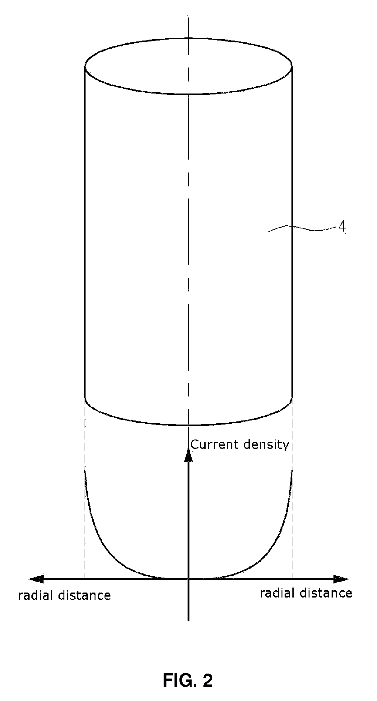
[0016]Accordingly, the present invention has been made keeping in mind the above problems occurring in the related art, and the present invention provides a current lead using Rutherford cables, in which Rutherford cables are radially arranged so that current flowing through the cross-sectional area of the current lead is uniformly distributed, thus realizing a relatively small cross-sectional area and enabling the application of a large amount of current.

Problems solved by technology

So, it is not easy to reduce the weight of the current lead.

Method used


Image

  • Current lead using rutherford cable
  • Current lead using rutherford cable
  • Current lead using rutherford cable

Examples


Embodiment Construction

[0030]Hereinafter, a detailed description will be given of the present invention, with reference to the appended drawings.

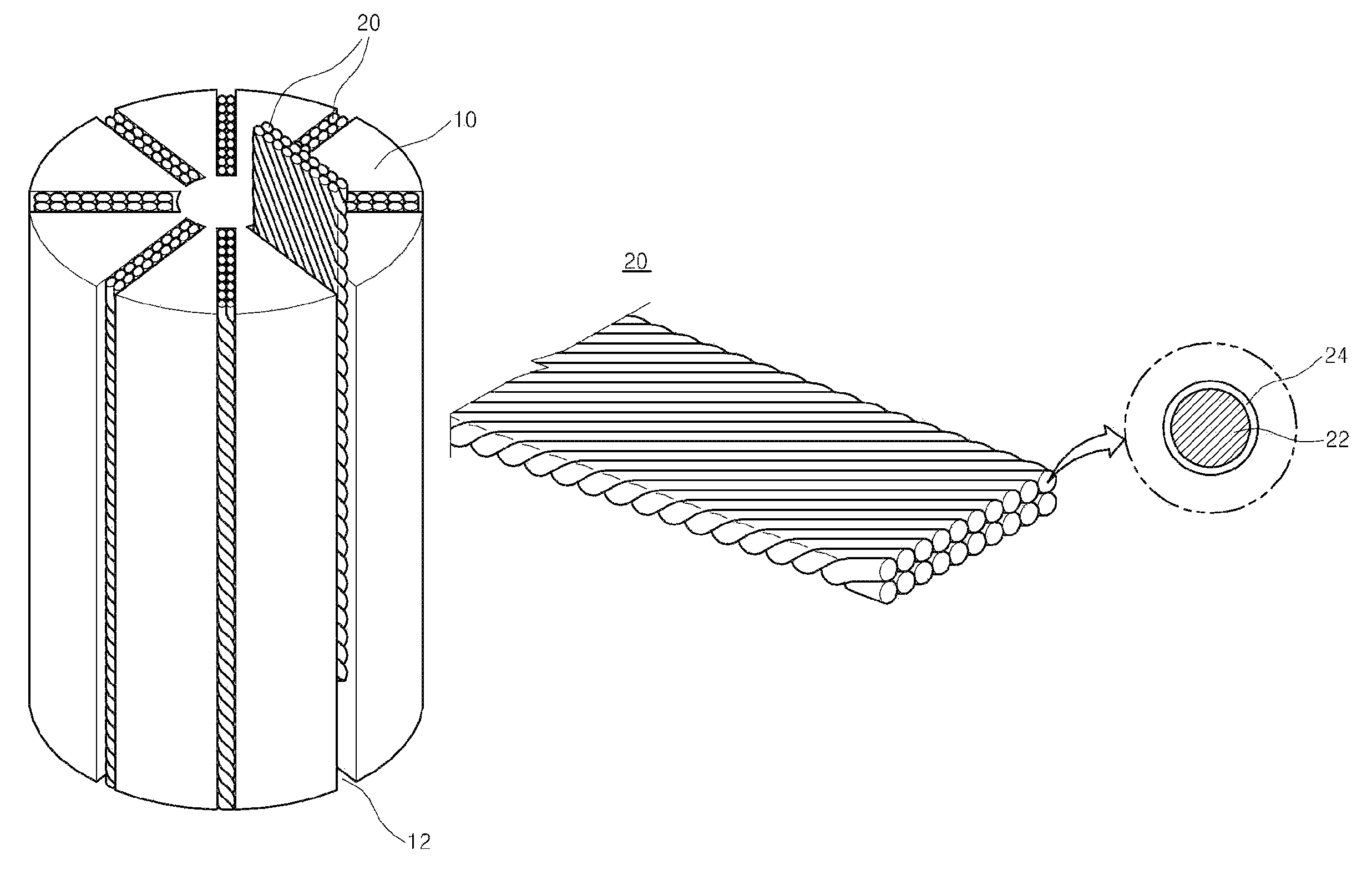
[0031]FIG. 3 is a view showing a current lead using Rutherford cables according to a preferred embodiment of the present invention, and FIG. 4 is a perspective view showing the Rutherford cable of FIG. 3.

[0032]According to the present invention, the current lead includes an insulating body 10 having a cylindrical shape or a polygonal prism shape and a plurality of Rutherford cables 20 in a bar form, in which the Rutherford cables 20 are radially arranged outward from the center of the insulating body 10.

[0033]In the present invention, the current lead indicates a normal conducting current lead.

[0034]The insulating body 10 is described below.

[0035]The insulating body 10 typically has a cylindrical shape or a polygonal prism shape, and preferably has a cylindrical shape from the structural point of view. When the current lead has a circular cross-section, Rutherfor...


PUM


Abstract

A normal conducting current lead using Rutherford cables, in which one end thereof is connected to an external power supplier and the other end thereof is connected to a superconducting current lead connected to a superconducting power apparatus operating at ultralow temperatures. The normal conducting current lead includes an insulating body, which has a cylindrical shape or a polygonal prism shape and a plurality of slots radially formed from the center thereof, and a plurality of Rutherford cables, which are inserted and fitted into the slots of the insulating body and are radially arranged so that a density of current flowing through the cross-section of the current lead is uniformly distributed.

Description

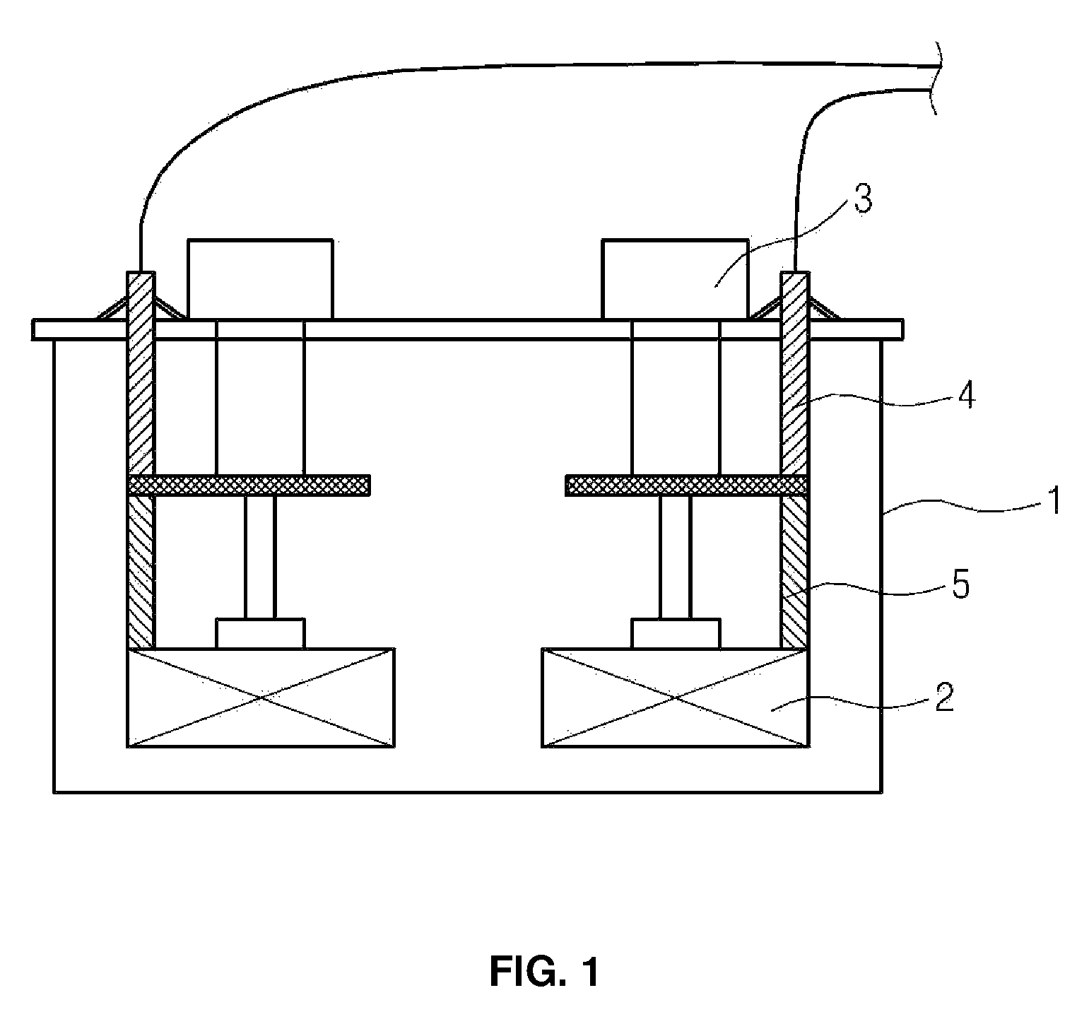
FIELD OF THE INVENTION[0001]The present invention relates to a current lead using Rutherford cables, and more particularly, to a current lead using Rutherford cables, which is suitable for use as a normal conducting current lead which connects an external power supplier and a superconducting power apparatus to supply current to the superconducting power apparatus and which causes current flowing through the cross-section of the normal conducting current lead to be uniformly distributed.BACKGROUND OF THE INVENTION[0002]Generally, a superconducting power apparatus which is operated at ultra-low temperatures is essentially composed of a current lead for supplying large current at from room temperature (300K) to an ultra-low temperature (77K).[0003]Specifically, FIG. 1 shows the structure of a general superconducting power apparatus. As shown in the drawing, the superconducting power apparatus received in an ultra-low temperature container 1 is connected with an ultra-low temperature fr...

Claims


Application Information

Patent Timeline
IPC IPC(8): H01B5/00
CPCH01B7/306H01B9/006H01B12/02H01B12/08H01B12/14
Inventor SIM, KI DEOKKIM, SEOK HOCHO, JEON WOOK
Owner LS CABLE & SYST LTD
Learn More