Method of determining the flatness of a foundation to which a building structure, machinery or equipment is to be mounted

a technology of flatness and foundation, applied in the field of method of determining the flatness of a foundation to which a, can solve the problems of complex devices and high cos

Inactive Publication Date: 2009-11-03
PRUTECHNIK DIETER BUSCH AG
View PDF11 Cites 2 Cited by
  • Summary
  • Abstract
  • Description
  • Claims
  • Application Information

AI Technical Summary

Problems solved by technology

These devices are quite complex and are very expensive.

Method used


Image

  • Method of determining the flatness of a foundation to which a building structure, machinery or equipment is to be mounted
  • Method of determining the flatness of a foundation to which a building structure, machinery or equipment is to be mounted
  • Method of determining the flatness of a foundation to which a building structure, machinery or equipment is to be mounted

Examples


Embodiment Construction

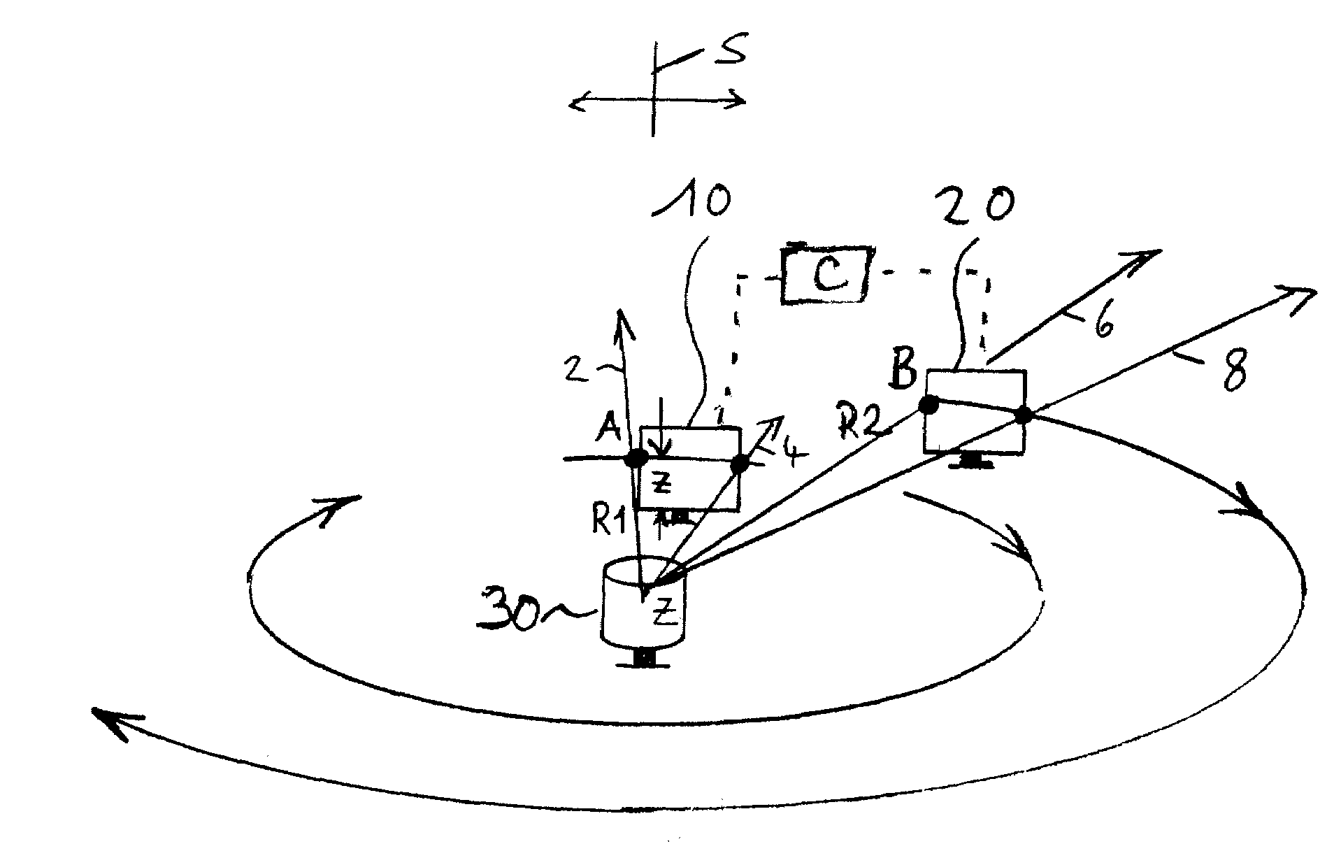
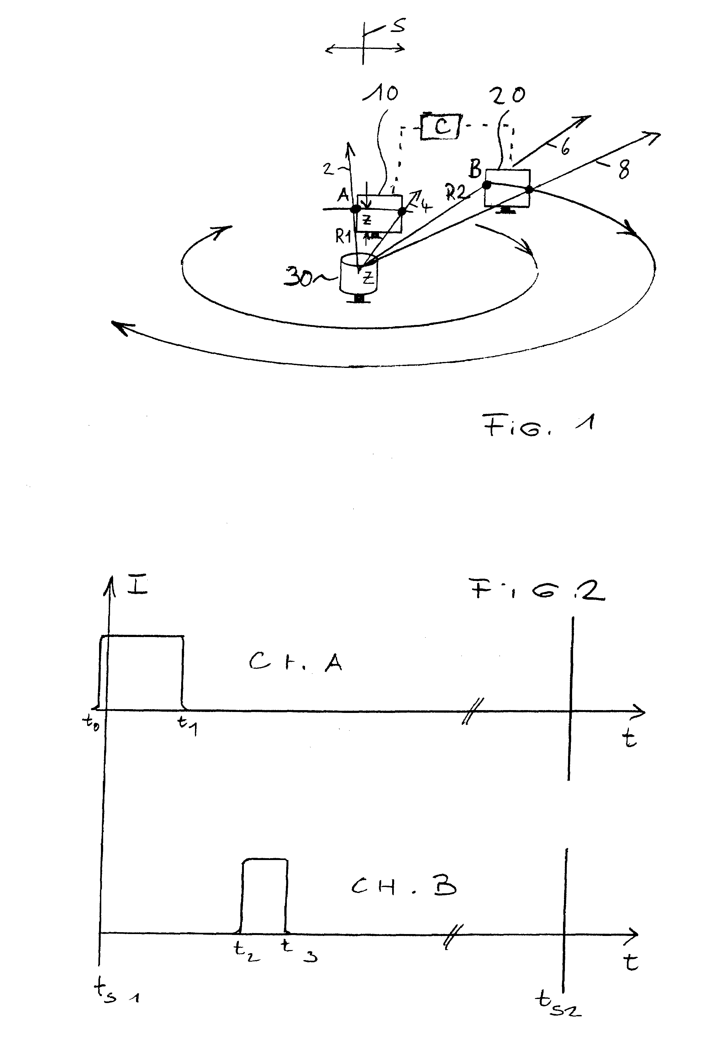
[0014]FIG. 1 schematically shows a laser beam that rotates in the horizontal plane AZB. To do this, a laser beam generator 30 is used that has a motorized means (not shown) with which a laser beam can be set into rotary motion around a central vertical axis Z. In this case, the laser beam moves successively into reference marked, mounting positions 2, 4, 6, and 8 (or however many positions at the machinery is to be fixed to the floor), which correspond the positions at which the legs of a piece of machinery that is to be installed on the factory floor are to be located in an essentially horizontally lying plane, which generally is parallel to the floor of the factory (which is almost never perfectly flat at the installation location). The motorized means is made such that a very constant angular velocity of the laser can be maintained so that, for example, the deviation of the laser beam from the actual angular position relative to the theoretical angular position at any given insta...


PUM


Abstract

A method for measuring flatness of a factory floor upon which machinery is to be mounted using a rotating laser beam that emits a rotating laser beam in an essentially horizontally plane. A photosensitive position sensor delivers an electrical pulse, which is identified by its timing and phase angle, during illumination by the laser beam. The phase angle and timing of these pulses constitute a measure of the position of the sensor in the coordinate system. Measurements are taken with the sensor positioned at each location at which the machinery is to be fixed to a factory floor. The method determines any differences in height between the measurement points and the amount, if any, that the floor needs to be adjusted at each mounting point to insure that a machine that is affixed to the floor these points will be level.

Description

BACKGROUND OF THE INVENTION[0001]1. Field of the Invention[0002]The invention relates to a method of using a laser-based position measuring device to determine the flatness of a foundation to which a structure, machinery or equipment is to be mounted. In particular, the invention relates to any situation where a building structure, machinery or equipment needs to be mounted in a level manner, such as a machine on a factory floor, particularly that of a newly built factory, a building on its foundation, a wind powered electrical generator on a mounting slab, etc. Thus, for purposes of this application, the term foundation should be viewed in its general sense as an underlying base or support, or a body or ground upon which something is built up or overlaid.[0003]2. Description of Related Art[0004]When installing machinery in a factory, especially in a newly built factory, before mounting of the machinery in place, e.g., by drilling holes to bolt down the feet of the machinery to the ...

Claims


Application Information

Patent Timeline
Patent Type & Authority Patents(United States)
IPC IPC(8): G01C3/08
CPCG01C15/002A61P25/00
Inventor KONETSCHNY, VOLKERSTROEL, KLAUS
Owner PRUTECHNIK DIETER BUSCH AG
Why Eureka
Try Eureka