
Geographic data collecting system

a technology for collecting system and geographic data, applied in the direction of instruments, navigation instruments, structural/machine measurement, etc., can solve the problems of inconvenient operation, inability to acquire images, and complicated procedures, and achieve the effect of improving working efficiency

Inactive Publication Date: 2007-01-11
KK TOPCON
View PDF19 Cites 71 Cited by
  • Summary
  • Abstract
  • Description
  • Claims
  • Application Information

AI Technical Summary

Benefits of technology

The present invention is a geographic data collecting system that includes a sensor that can collect information about the movement of an object. The system also includes a gyro sensor that can detect the direction in which the sensor is moving. This allows the operator to easily move from one point to another and collect data with greater efficiency. The technical effect of this invention is to provide a more convenient and efficient way to collect geographic data.

Problems solved by technology

The technical problem addressed in this patent is how to efficiently gather accurate geographic data needed for creating detailed maps that include image data. Conventional methods require multiple steps and equipment to measure distances and angles from an operator's perspective, making it difficult to quickly accumulate enough data. Existing systems either lack precision or have complex procedures requiring separate imaging devices.

Method used


Image

  • Geographic data collecting system
  • Geographic data collecting system
  • Geographic data collecting system

Examples


Embodiment Construction

[0019] Description will be given below on the best mode for carrying out the present invention referring to the drawings.

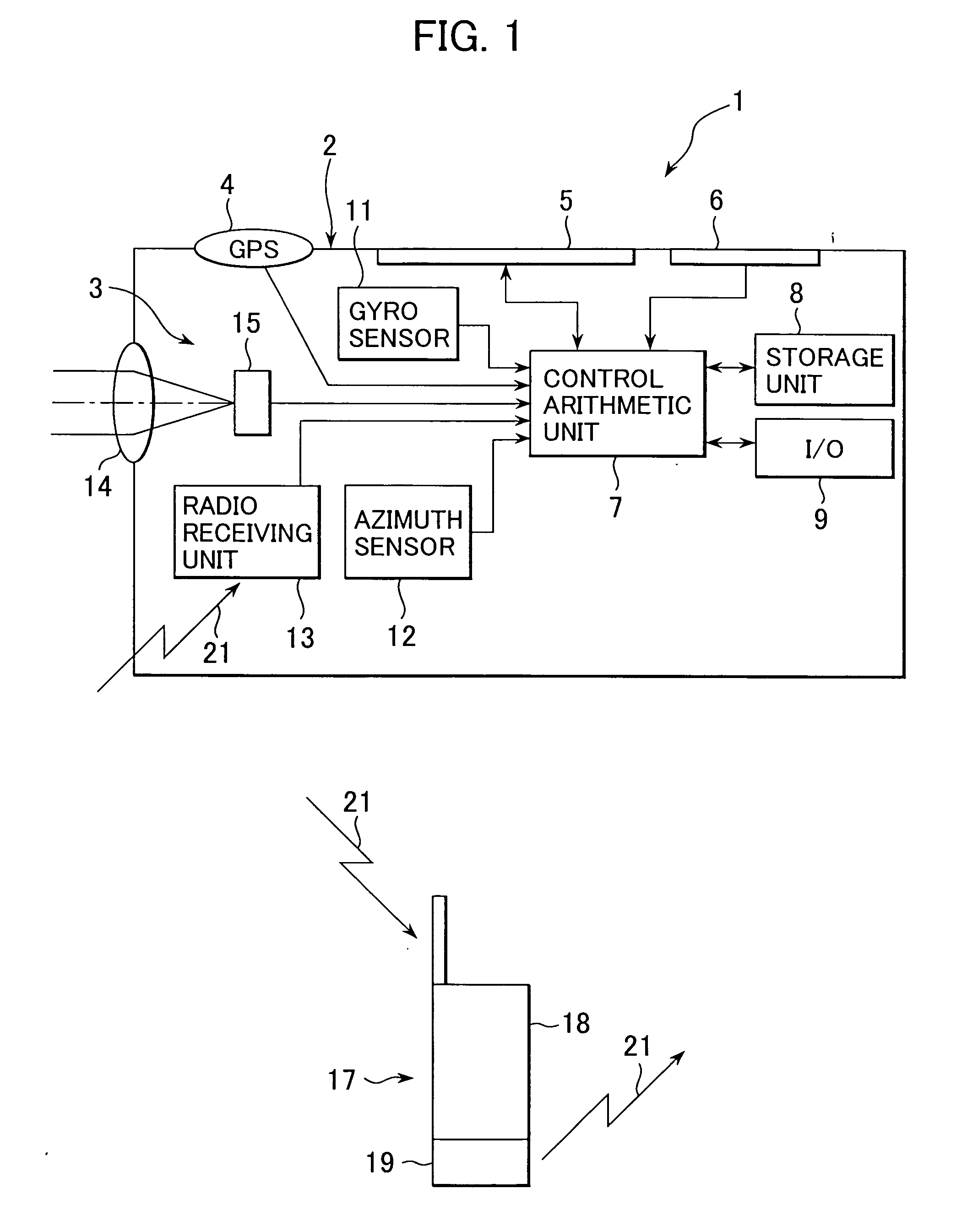
[0020] Referring to FIG. 1, description will be given on a geographic data collecting system 1 according to the present invention.

[0021] In the figure, reference numeral 2 denotes a portable housing. In the housing 2, there are provided an image pickup unit 3, a GPS unit 4, a display unit 5, and an operation unit 6. Inside the housing 2, there are provided a control arithmetic unit 7, a storage unit 8, an input / output control unit 9, a gyro sensor 11, an azimuth sensor 12, and a radio receiving unit 13. The image pickup unit 3 comprises an objective lens 14, and an image pickup element 15 comprising an assembly of a multiple of pixels such as a CCD, a CMOS sensor, etc. The image pickup element 15 can specify address of each individual pixel (position in the image pickup element). An image of an object formed in the image pickup element 15 is outputted to the con...


PUM


Abstract

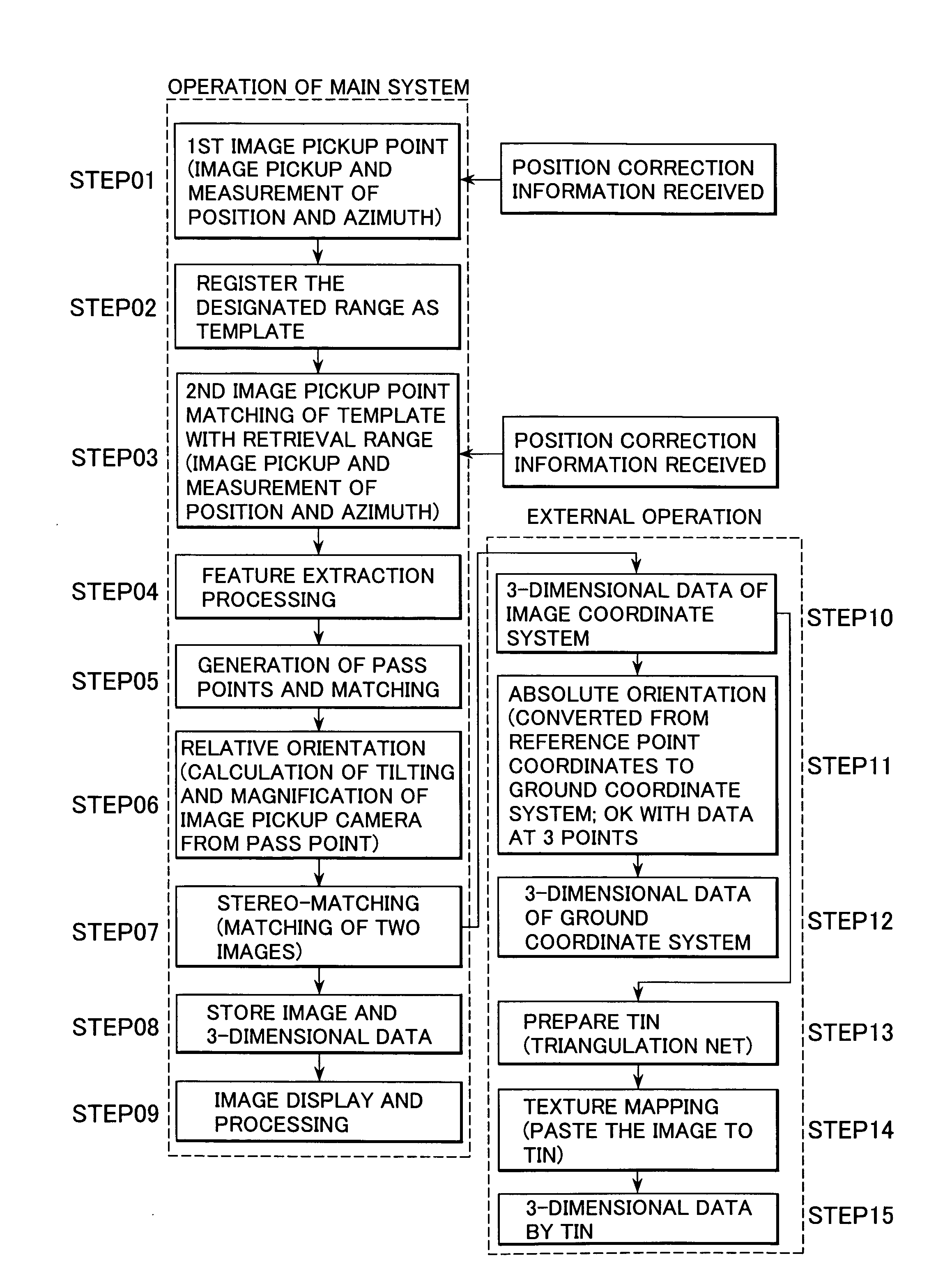
A geographic data collecting system, comprising an image pickup unit for taking a digital image including a measuring point of an object to be measured, a GPS unit, an azimuth sensor for detecting an image pickup direction, a display unit for displaying the image taken, a receiving unit for receiving correction information to correct measurement result of the GPS unit, and a control arithmetic unit for obtaining corrected position data by correcting the measurement result based on the correction information and for associating the image acquired by the image pickup unit with the corrected position data and for storing the image and the corrected position data in a storage unit.

Description


Claims


Application Information

Patent Timeline
Owner KK TOPCON
Learn More