Ceramic honeycomb filter

a honeycomb filter and ceramic honeycomb technology, applied in the field of ceramic honeycomb filter, can solve the problems of reducing the capture efficiency, increasing the pressure loss, and reducing the engine output, and achieves the effects of ensuring a long particulate-capture time, excellent mechanical strength and durability, and low pressure loss

Inactive Publication Date: 2004-12-07
HITACHI METALS LTD +1
View PDF26 Cites 73 Cited by
  • Summary
  • Abstract
  • Description
  • Claims
  • Application Information

AI Technical Summary

Benefits of technology

Accordingly, an object of the present invention is to provide a ceramic honeycomb filter having excellent mechanical strength and durability as well as low pressure loss, which ensures a long particulates-capturable time.
The pore-forming material is substantially spherical, pores formed in the partition walls are also spherical, resulting in decrease in stress concentration in the pores. Therefore, the use of a spherical pore-forming material can provide a honeycomb structure with excellent mechanical strength. Further, when the pore-forming material is hollow, it is easy to burn the pore-forming material away, avoiding the cracking of the partition walls at the time of burning the pore-forming material, which leads to improvement in a production yield.

Problems solved by technology

When the captured particulates are excessively accumulated in the ceramic honeycomb filter 11, the pressure loss of the filter 11 increases, likely resulting in decrease in an engine output.
The capturing efficiency and the pressure loss are in a contradictory relation; the higher capturing efficiency results in increase in the pressure loss, while decrease in the pressure loss results in the reduction of the capturing efficiency.
Though a good balance between the pressure loss and the particulates-capturing efficiency of a filter can be achieved to some extent by optimizing the porosity and the average pore diameter of a ceramic honeycomb structure and the pore diameters of its partition walls, however, increase in the porosity and the average pore diameter inevitably results in decrease in the strength of the porous partition walls of the filter.
Accordingly, it has been impossible to obtain ceramic honeycomb filters having low pressure loss and high capturing efficiency as well as high durability, which are not broken by thermal stress and shock generated when used as particulates-capturing filters for diesel engines, or by mechanical stress generated by fastening in assembling and vibration, etc.
Accordingly, there is a large temperature gradient between a center portion of the filter 11 and an outer periphery portion, resulting in the problems that the filter is cracked by thermal stress, and that particulates are insufficiently burned because there is no enough temperature increase in the outer periphery portion.
When there is a large accumulation of particulates, flow paths are clogged on the exhaust-gas-entering side, resulting in increase in the pressure loss of the filter.
As a result, the particulates-capturable time becomes shorter, thereby making it necessary to regenerate the filter frequently.

Method used


Image

  • Ceramic honeycomb filter
  • Ceramic honeycomb filter
  • Ceramic honeycomb filter

Examples


reference example 1

1 AND 2, REFERENCE EXAMPLE 1

To form cordierite having a main component composition comprising 49-51% by mass of SiO.sub.2, 35-37% by mass of Al.sub.2 O.sub.3 and 13-15% by mass of MgO, kaolin powder, calcined kaolin powder, alumina powder, aluminum hydroxide powder, silica powder and talc powder were mixed together with a binder, a lubricant and spherical resin powder as a pore-forming material in predetermined amounts. The resultant mixture was mixed with water to form a plasticizable batch. This batch was extrusion-molded to a cylindrical honeycomb shape, and dried.

The particle diameter distribution of the spherical resin powder used as the pore-forming material is shown in FIG. 16. The average particle diameter and the percentage of particle diameter in 20-100 .mu.m of the spherical resin powder are shown in Table below.

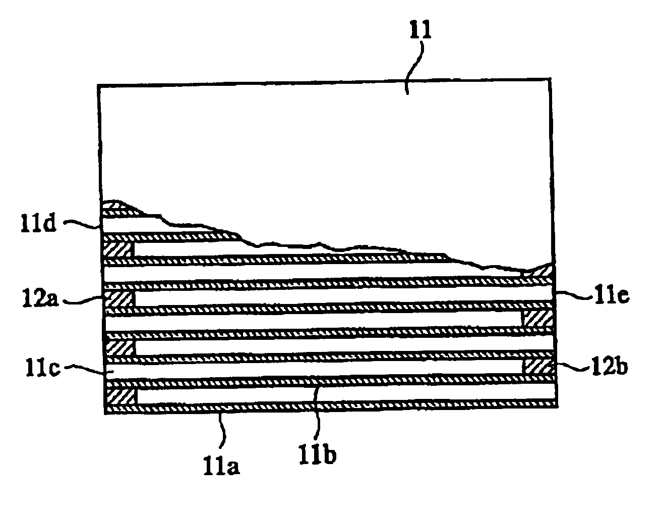
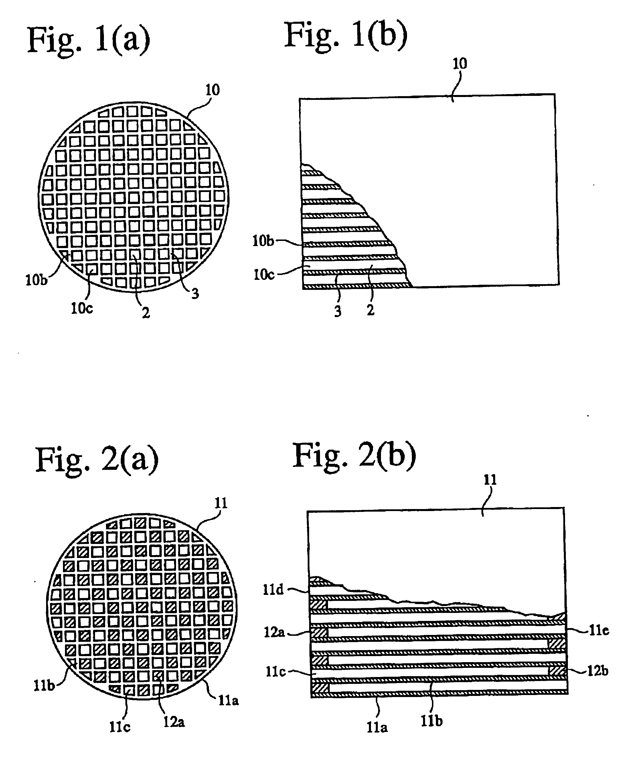
The resultant green body was sintered at a temperature of 1350-1440.degree. C. to obtain various types of cordierite honeycomb structures 10 each comprising porou...

examples 3-7

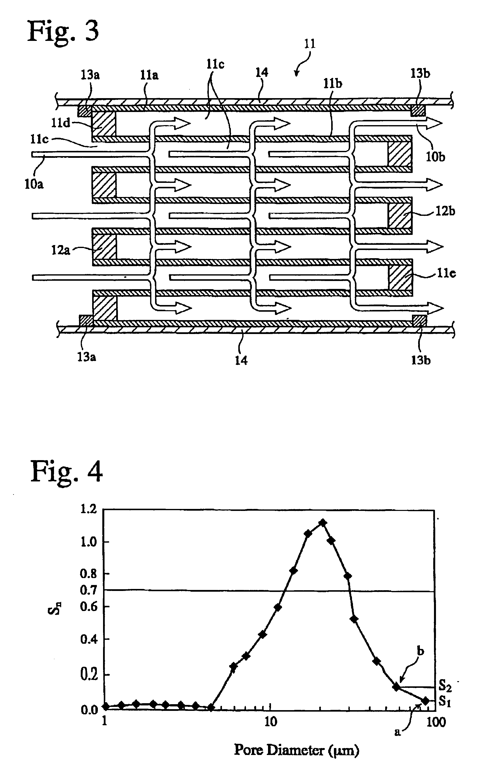
The same plasticizable batch as in Example 1 was produced, and this batch was molded to a cylindrical honeycomb structure by an extrusion-molding method. The size of a molding die was adjusted to provide various partition wall thickness and various numbers of flow pats per 1 cm.sup.2. Each green body was sintered at a temperature of 1350-1440.degree. C., to obtain cordierite honeycomb structures of Examples 3-7 each having porous partition walls and penetrating pores for flow paths. Each honeycomb structure had a diameter of 143 mm and a length of 152 nm with partition wall thickness of 0.15-0.33 mm, the number of flow paths per 1 cm.sup.2 being 39-62. Also, each honeycomb structure had a porosity of 65% and an average pore diameter of 20.8%, the maximum of the slope S.sub.n of its cumulative pore volume curve being 1.12.

Both ends of each filter were sealed in the same manner as in Example 1 to produce a cordierite honeycomb filter. The pressure loss and fracture resistance of each ...

examples 8 and 9

, REFERENCE EXAMPLE 2

As a ceramic material with a high specific surface area, activated alumina powder having a center particle size of 5 .mu.m and alumina sol were mixed with water to form an activated alumina slurry. This slurry was wash-coated onto the same ceramic honeycomb structures as in Examples 1 and 2 and Reference Example 1. After removing an excess slurry, the coating of a slurry was repeated, and a 60 g / L of activated alumina was finally coated onto the honeycomb structure. After the honeycomb structure was dried at 120.degree. C., it was sintered at 800.degree. C. Further, each honeycomb structure was immersed in an aqueous chloroplatinic acid solution, dried at 120.degree. C., and then sintered at 800.degree. C. Ceramic honeycomb filters each carrying about 2 g / L of a platinum catalyst were thus obtained.

The ceramic honeycomb filter carrying a platinum catalyst was measured with respect to pressure loss in the same manner as in Example 1. The pressure loss after carry...


PUM

PropertyMeasurementUnit
pore diameteraaaaaaaaaa
porosityaaaaaaaaaa
porosityaaaaaaaaaa

Abstract

A ceramic honeycomb filter comprising a ceramic honeycomb structure having porous partition walls defining a plurality of flow paths for flowing an exhaust gas through the porous partition walls to remove particulates from the exhaust gas, the predetermined flow paths among the flow paths being sealed at their ends, a catalyst being carried by the porous partition walls, the porous partition walls having a porosity of 60-75% and an average pore diameter of 15-25 mum when measured according to a mercury penetration method, and the maximum of a slope Sn of a cumulative pore volume curve of the porous partition walls relative to a pore diameter obtained at an n-th measurement point being 0.7 or more, the Sn being represented by the following formula (1):wherein Dn is a pore diameter (mum) at an n-th measurement point, Dn-1 is a pore diameter (mum) at an (n-1)-th measurement point, Vn is a cumulative pore volume (cm<3> / g) at an n-th measurement point, and Vn-1 is a cumulative pore volume (cm<3> / g) at an (n-1)-th measurement point.

Description

The present invention relates to a ceramic honeycomb filter for removing particulates from an exhaust gas from diesel engines.BACKGROUND OF THE OPTIONTo remove particulates from an exhaust gas emitted from diesel engines, investigation has been made to use ceramic honeycomb filters having porous partition walls through which the exhaust gas containing particulates is caused to flow. Such filters are called particulates-capturing filters (diesel particulate filters). FIG. 2(a) is a front view showing a ceramic honeycomb filter 11 as a particulates-capturing filter, FIG. 2(b) is a partially cross-sectional side view showing the ceramic honeycomb filter 11 of FIG. 2(a), and FIG. 3 is a schematic cross-sectional view showing the ceramic honeycomb filter 11 of FIG. 2. As shown in FIGS. 2 and 3, a substantially cylindrical ceramic honeycomb filter 11 comprises an outer peripheral wall 11a, and porous partition walls 11b disposed inside the outer peripheral wall 11a, with flow paths 11c su...

Claims


Application Information

Patent Timeline
Patent Type & Authority Patents(United States)
IPC IPC(8): B01D46/24B01J35/04B01J35/00C04B38/00F01N3/022F01N3/035
CPCB01D46/0001B01D46/2455B01D46/2459B01D46/2462B01J35/04C04B38/0006F01N3/035B01D46/2429C04B35/195C04B38/0012C04B38/0054C04B38/0074Y10S55/10B01D46/2451B01D46/2466B01D2046/2433B01D2046/2437B01D2046/2488B01D2046/2496B01D2279/30B01J35/1033B01J35/1076C04B2111/00198C04B2111/00793Y10S55/30B01D46/2498B01D46/24492B01D46/24491B01D46/2482B01D46/247
Inventor SUWABE, HIROHISAOTSUBO, YASUHIKOTOKUMARU, SHINYAFUNABASHI, HIROSHINAKAGOME, KEIICHITSUJITA, MAKOTOTORISAKA, HISAKI
Owner HITACHI METALS LTD
Why Eureka
Try Eureka