Dipole locator using multiple measurement points

a technology of dipole locators and measurement points, applied in the direction of instruments, instruments, borehole/well accessories, etc., can solve the problems of not being able to use the left-right determination in front of or behind the transmitter, and no satisfactory method of simultaneously locating the transmitter in both fore-aft and back

Active Publication Date: 2006-11-16
CHARLES MACHINE WORKS
View PDF5 Cites 70 Cited by
  • Summary
  • Abstract
  • Description
  • Claims
  • Application Information

AI Technical Summary

Problems solved by technology

However, the left-right determination can only be used either in front of or behind the transmitter because there is no y component to the dipole field when the receiver is directly above the transmitter (such

Method used


Image

  • Dipole locator using multiple measurement points
  • Dipole locator using multiple measurement points
  • Dipole locator using multiple measurement points

Examples


Embodiment Construction

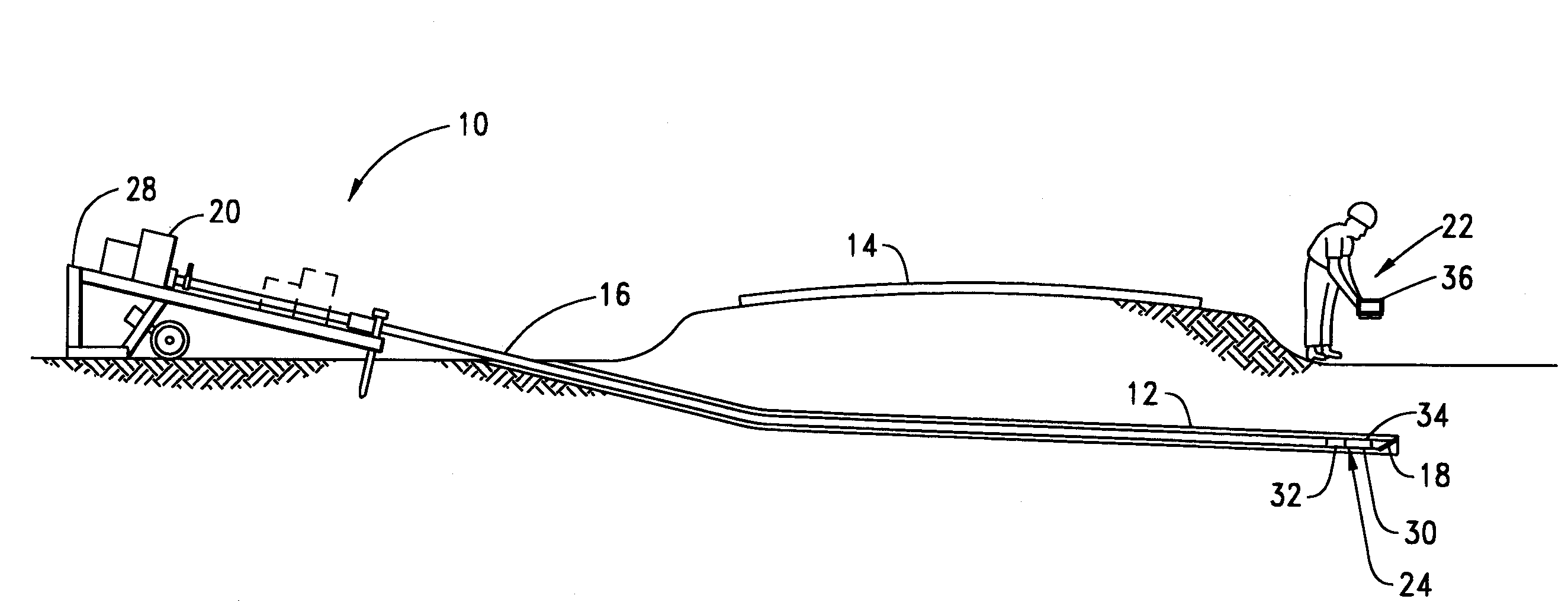
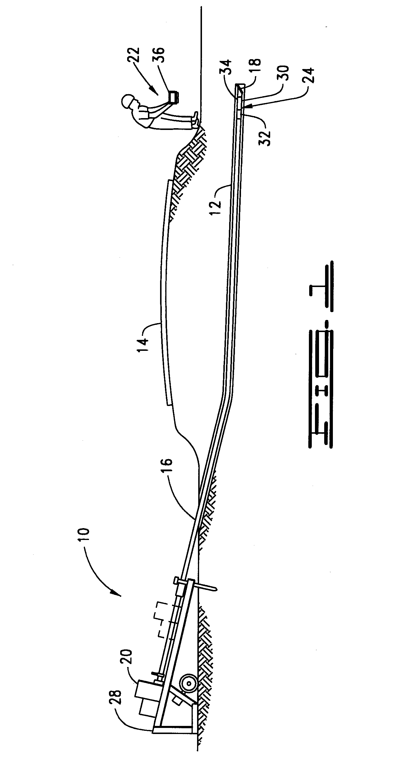
[0023] With reference now to the drawings in general, and FIG. 1 in particular, there is shown therein a horizontal directional drilling system (“HDD”) system 10 for use with the present invention. FIG. 1 illustrates the usefulness of horizontal directional drilling by demonstrating that a borehole 12 can be made without disturbing an above-ground structure, namely a roadway or walkway as denoted by reference numeral 14. To cut or drill the borehole 12, a drill string 16 carrying a drill bit 18 is rotationally driven by a rotary drive system 20. When the HDD system 10 is used for drilling a borehole 12, monitoring the position of the drill bit 18 is critical to accurate placement of the borehole and subsequently installed utilities. The present invention is directed to a system 22 and method for tracking and monitoring a downhole tool assembly 24 during a horizontal directional drilling operation.

[0024] The HDD system 10 of the present invention is suitable for near-horizontal subs...


PUM


Abstract

A receiver and tracking system for identifying a location of a magnetic field source. In a preferred embodiment a plurality of tri-axial antennas are positioned at three distinct points on a receiver frame. Each antenna detects a magnetic field from a source and a processor is used to determine a location of the source relative to the frame using the antenna signals. Each tri-axial antenna comprises three windings in each of three channels defined by a support structure. The windings each define an aperture area. The windings have substantially identical aperture areas and have a common center point. The receiver may to display to the operator the relative location of the field source or may direct the operator to a spot directly above the field source.

Description

CROSS REFERENCE TO RELATED APPLICATION [0001] This application claims the benefit of U.S. Application No. 60 / 680,780, filed May 13, 2005 and U.S. Application No. 60 / 728,066, filed Oct. 19, 2005, the contents of which are incorporated fully herein by reference.FIELD OF THE INVENTION [0002] The present invention relates generally to the field of locating underground objects, and in particular to locating and tracking a beacon within the field of operation of a horizontal drilling machine. SUMMARY OF THE INVENTION [0003] The present invention is directed to a receiver system for identifying a location of a magnetic field source. The receiver comprises a frame, a first antenna assembly supported by the frame, a second antenna assembly supported by the frame, a third antenna assembly supported by the frame, and a processor. Each antenna assembly is adapted to detect the magnetic field from the source. The processor is adapted to receive an antenna signal from each of the antenna assembli...

Claims


Application Information

Patent Timeline
IPC IPC(8): E21B47/02
CPCE21B47/02224G01V3/081G01V3/165H01Q7/00H01Q21/24H01Q1/04E21B47/0232
Inventor COLE, SCOTT B.GARD, MICHAEL F.BROWN, DAVID R.MARSHALL, BRADLEY S.
Owner CHARLES MACHINE WORKS
Why Eureka
Try Eureka