

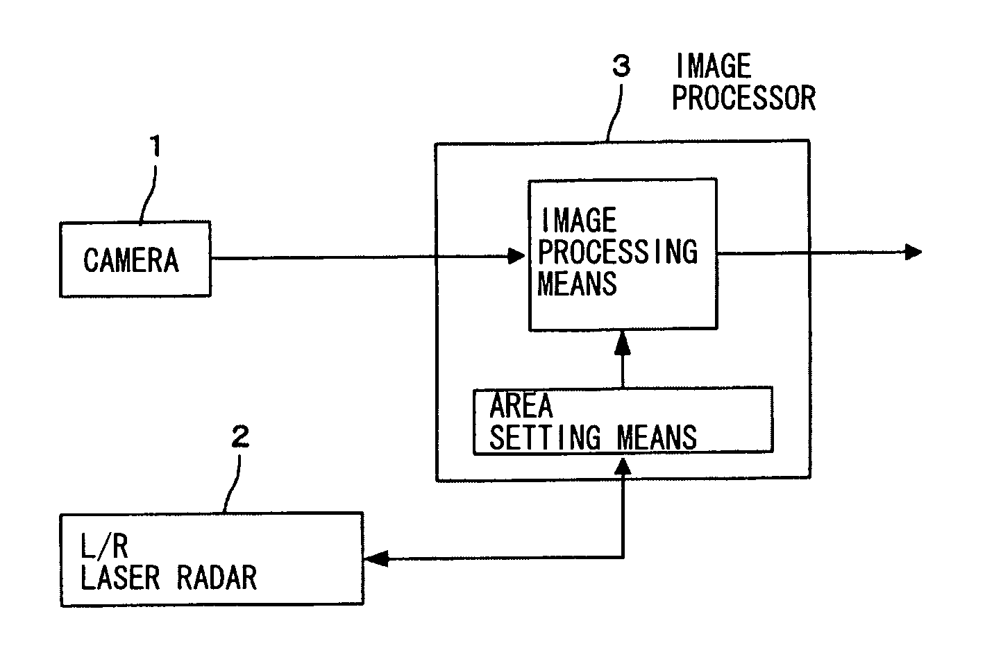
Image processing system for mounting to a vehicle
a technology for mounting to vehicles and images, applied in the field of image processing systems, can solve the problems of inability to accurately determine the type of detected objects, time-consuming image processing, and inability to obtain real-time response easily, so as to reduce the size of the image processing area, increase the distance to the object detected by the radar, and facilitate the effect of setting
- Summary
- Abstract
- Description
- Claims
- Application Information
AI Technical Summary
Benefits of technology
Problems solved by technology
Method used
Image

Examples
second embodiment
[0063]Next, an image processor according to the invention is described, which is characterized as further limiting the image processing area on the lower edge side in the vertical direction along which scanning is not carried out.
[0064]An image processor according to the second embodiment carries out the following process between Steps S10 and S11 of the flowchart of FIG. 7.
[0065]Firstly, as shown in FIG. 8A, a reference plane 11 is defined parallel to the surface of the road supporting one's own vehicle (which may be the road surface itself). If the camera 1 is set parallel to this road surface, this plane 11 may be characterized by the height Xc in the aforementioned camera-fixed coordinate system (Xc, Yc, Zc), representing the height of the optical axis of the camera 1 from the road surface on which is one's own vehicle. If the road is flat, as shown in FIG. 8A, this plane 11 is also parallel to the road surface at the position of a front-going vehicle 10.
[0066]Next, a measuremen...
third embodiment
[0069]Next, FIG. 12 is referenced to describe the invention adapted to reduce the size of the image processing area (or the spread of the beam cross-section) as the distance to the object measured by the radar 2 increases.
[0070]According to this embodiment, the image processor 3 carries out any of the following processes (Processes 1, 2 and 3) in Step S3 of the flowchart of FIG. 7.
[0071]Process 1 is that of changing the radius “a” of the beam according to the distance ZL obtained in Step S2 as the result of measurement by the radar based on Formula (4) shown below:
[0072]a′=K1d′-daFormula(4)
where a is the beam radius before the change, a′ is the beam radius after the change, d is a standard distance, d′ is a distance as result of measurement (as shown in FIGS. 12A and 12B) and K1 is a constant for adjustment.
[0073]Process 2 is that of changing the beam radius according to the distance ZL such that the cross-sectional area of the beam will change as shown by Formula (5) given bel...
fourth embodiment
[0078]Next, the invention is explained according to which the image processor 3 carries out a correction process as will be explained below between Steps S2 and S3 of the flowchart of FIG. 7 such that the position of the image processing area is adjusted according to the angle between the central axes of the camera 1 and the radar 2.
[0079]Let dθ indicate the angle in the vertical direction between the central axes of the camera 1 and the radar 2 as shown in FIG. 14A. In this situation, the coordinate of each measurement point Ci in the vertical direction (XL) is changed from H to H+ZL·tan(dθ).
[0080]If the coordinate conversion formula is set under the condition where the central axes of the camera 1 and the radar 2 are parallel as shown in FIG. 13A, the position of the beam area (that is, the position of the image processing area) remains proper as shown in FIG. 13B as long as these central axes remain parallel to each other. If the central axes of the camera 1 and the radar 2 cease...
PUM
 Abstract
Description
Claims
Application Information