
Third-order optical autocorrelator for time-domain operation at the telecommunication wavelengths

a time-domain, time-domain technology, applied in the direction of camera filters, instruments, lighting and heating apparatuses, etc., can solve the problems of limited wavelength tunability range, polarization sensitive second-order nonlinear processes, and limited sensitivity of second-order autocorrelation when invoking symmetrical functions

Inactive Publication Date: 2009-11-03
THE ARIZONA BOARD OF REGENTS ON BEHALF OF THE UNIV OF ARIZONA
View PDF8 Cites 0 Cited by
  • Summary
  • Abstract
  • Description
  • Claims
  • Application Information

AI Technical Summary

Benefits of technology

[0008]One object of the present invention is to provide a technique for the derivation of amplitude and phase information from short laser pulses without the necessity of coupling a spectrometer to a highly sensitive detector.
[0010]Still another object of the present invention is to provide an optical material in which a conversion efficiency is achieved without the use of phase matching and / or without the use of quadratic nonlinear effects.
[0011]Accordingly, one object of the present invention is to provide an optical material in which third harmonic generation occurs within a thin film organic polymer, thus providing a low cost, sensitive third-order autocorrelator that can be used to ascertain a laser pulse amplitude and phase.

Problems solved by technology

However, second order nonlinear processes suffer from limited sensitivity and are specific only to particular pulse shapes.
For instance, second-order autocorrelations when invoking symmetrical functions do not provide information on asymmetric pulses.
Furthermore, since second-harmonic signals are typically generated in thick crystals in a geometry that satisfies phase-matching conditions, second order nonlinear process are polarization sensitive and have a limited wavelength tunability range.
However, third-order nonlinear processes are generally limited in sensitivity due to the lack of materials with both a strong third-order nonlinearity and transparency.
The sensitivity of a third-order autocorrelation using three-photon absorption is somewhat limited.
However, such pulse measurement and methods conventionally have required spectrometers coupled to expensive highly sensitive detector arrays.

Method used


Image

  • Third-order optical autocorrelator for time-domain operation at the telecommunication wavelengths
  • Third-order optical autocorrelator for time-domain operation at the telecommunication wavelengths
  • Third-order optical autocorrelator for time-domain operation at the telecommunication wavelengths

Examples


Embodiment Construction

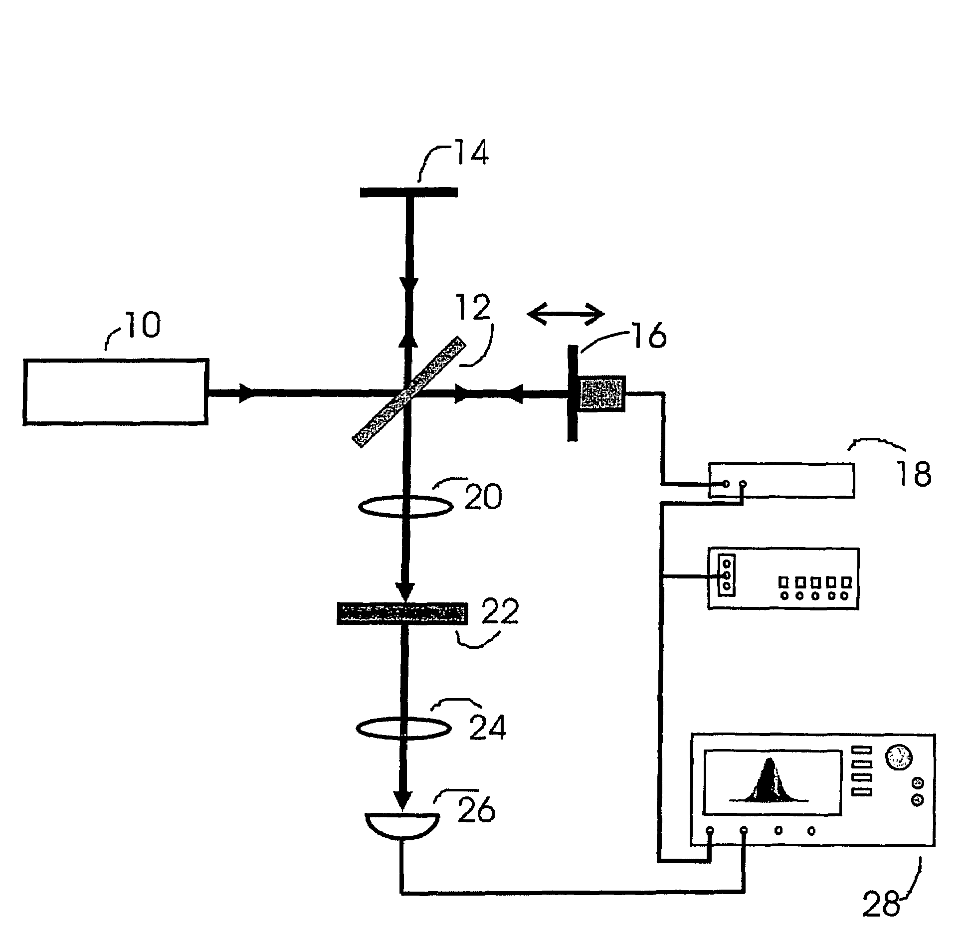
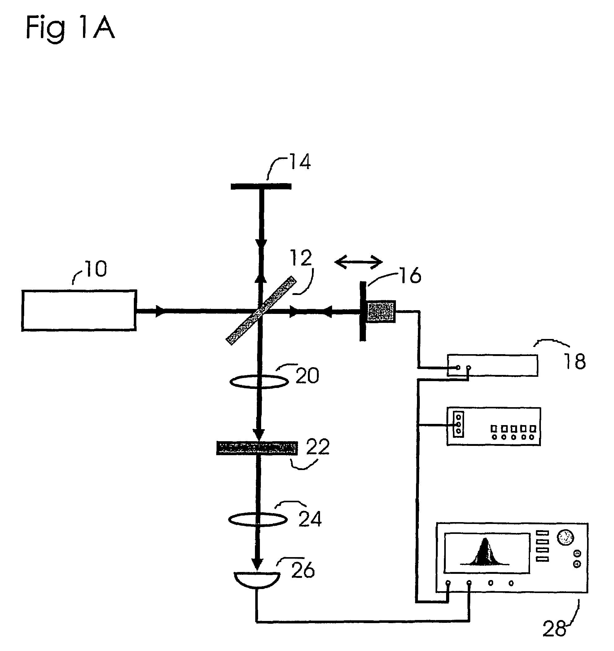
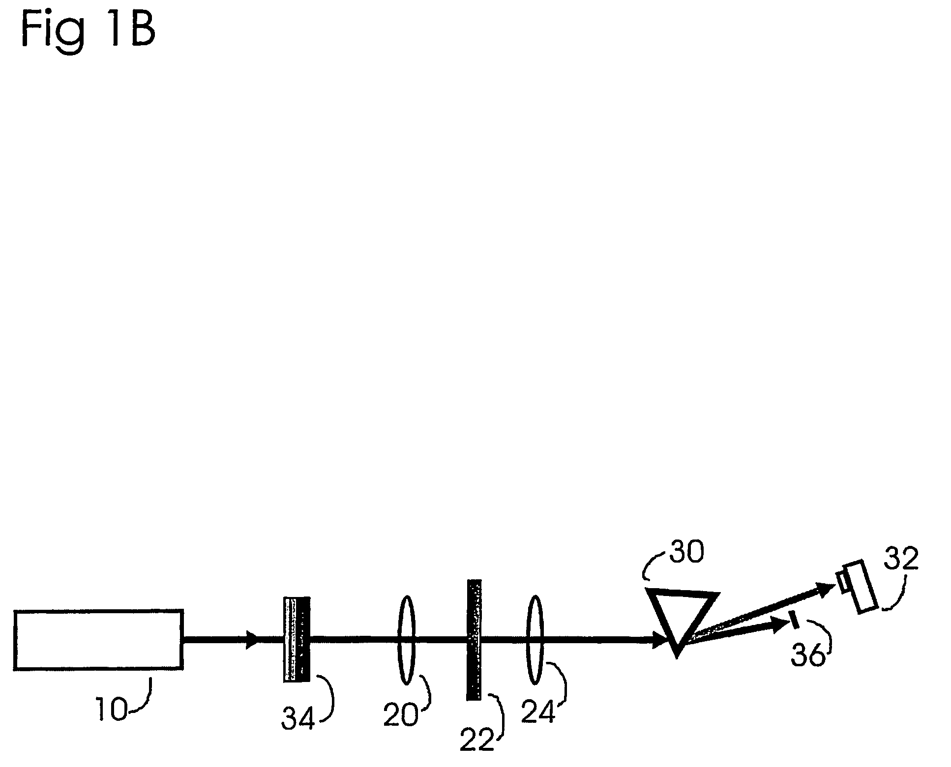
[0025]Referring now to the drawings, wherein like reference numerals designate identical, or corresponding parts throughout the several views, and more particularly to FIG. 1A thereof, FIG. 1A is a depiction of an optical apparatus according to the present invention utilizing third harmonic generation to produce from a thin film chromophore sample a correlation to the optical pulse.

[0026]As shown in FIG. 1A, an optical source 10 (e.g., a pulse laser) generates an optical pulse at a wavelength λ. The optical pulse is directed into a divider which receives and divides the pulse into two parts (preferably of equal intensity), at least one part being time delayed from the other part. One part of the divided beam as illustrated in FIG. 1 is divided by the beam splitter 12 and reflected from a stationary mirror 14. The other part of the divided beam as illustrated in FIG. 1 is divided by the beam splitter 12 and reflected from a displaceable mirror 16. In one embodiment of the present inv...


PUM

PropertyMeasurementUnit
absorption coefficientaaaaaaaaaa
time resolutionaaaaaaaaaa
thickaaaaaaaaaa

Abstract

A device and method for producing a third harmonic signal from an optical pulse of wavelength k. In the device and method, an optical pulse at a wavelength k is incident on a material including at least one molecule having a formula D—U—A, where D is an electron donor group, A is an electron acceptor group, and Π is a conjugated structure having it bonds that connect D to A. The molecule exhibits a strong absorption band centered at a wavelengthko and a weakly absorbing region centered at a wavelength k, which is less than Xo. A wavelength k / 2 has a value of about Xo, and a wavelength k / 3 has a value of about X1. A third harmonic signal at k / 3 is generated. From a measured third harmonic signal as a function of a time delay for separate optical pulses entering the material, at least one of a pulse width and a pulse shape of the optical pulse can be extracted. From a spectrally resolved third harmonic signal, a phase of the optical pulse can be extracted.

Description

DISCUSSION OF THE BACKGROUND[0001]1. Field of the Invention[0002]This invention relates to the field of ultra-fast laser operation and the characterization of optical pulses.[0003]2. Background of the Invention[0004]Within the research field of ultrashort-pulse lasers and more generally within ultrafast science and technology, there is a need to develop and implement a range of diagnostic techniques for characterizing ultrashort optical pulses that have durations of femtoseconds (fs). At limits where pulses can be shorter than 10 fs, the diagnostics used for quantitative assessments must exhibit a time resolution in the region of ifs. Indeed, driving the development for better characterization has been the continued development of ultra-fast lasers with increasing gains in power and portability. For example, driven by the development of all optical networks with increasing bandwidth, mode-locked erbium doped fiber lasers that emit sub-picosecond pulses at the telecommunication wavel...

Claims


Application Information

Patent Timeline
Patent Type & Authority Patents(United States)
IPC IPC(8): G02F2/02G02F1/35G02F1/361
CPCG02F1/353G02F1/3532G02F1/3615G02F1/3614G02F2001/354G02F1/354
Inventor RAMOS-ORTIZ, GABRIELCHA, MYOUNGSIKMARDER, SETH R.KIPPELEN, BERNARD
Owner THE ARIZONA BOARD OF REGENTS ON BEHALF OF THE UNIV OF ARIZONA
Learn More