
Wire harness water cut-off structure

a wire harness and cut-off technology, applied in contact members penetrating/cutting insulation/cable strands, electrical/fluid circuits, vehicle components, etc., can solve the problems of difficult to promote a productivity, complex structure, and inability to prevent, so as to reduce the inner diameter of the tube, reduce the effect of water invasion and simple structur

Inactive Publication Date: 2009-11-10
YAZAKI CORP
View PDF10 Cites 8 Cited by
  • Summary
  • Abstract
  • Description
  • Claims
  • Application Information

AI Technical Summary

Benefits of technology

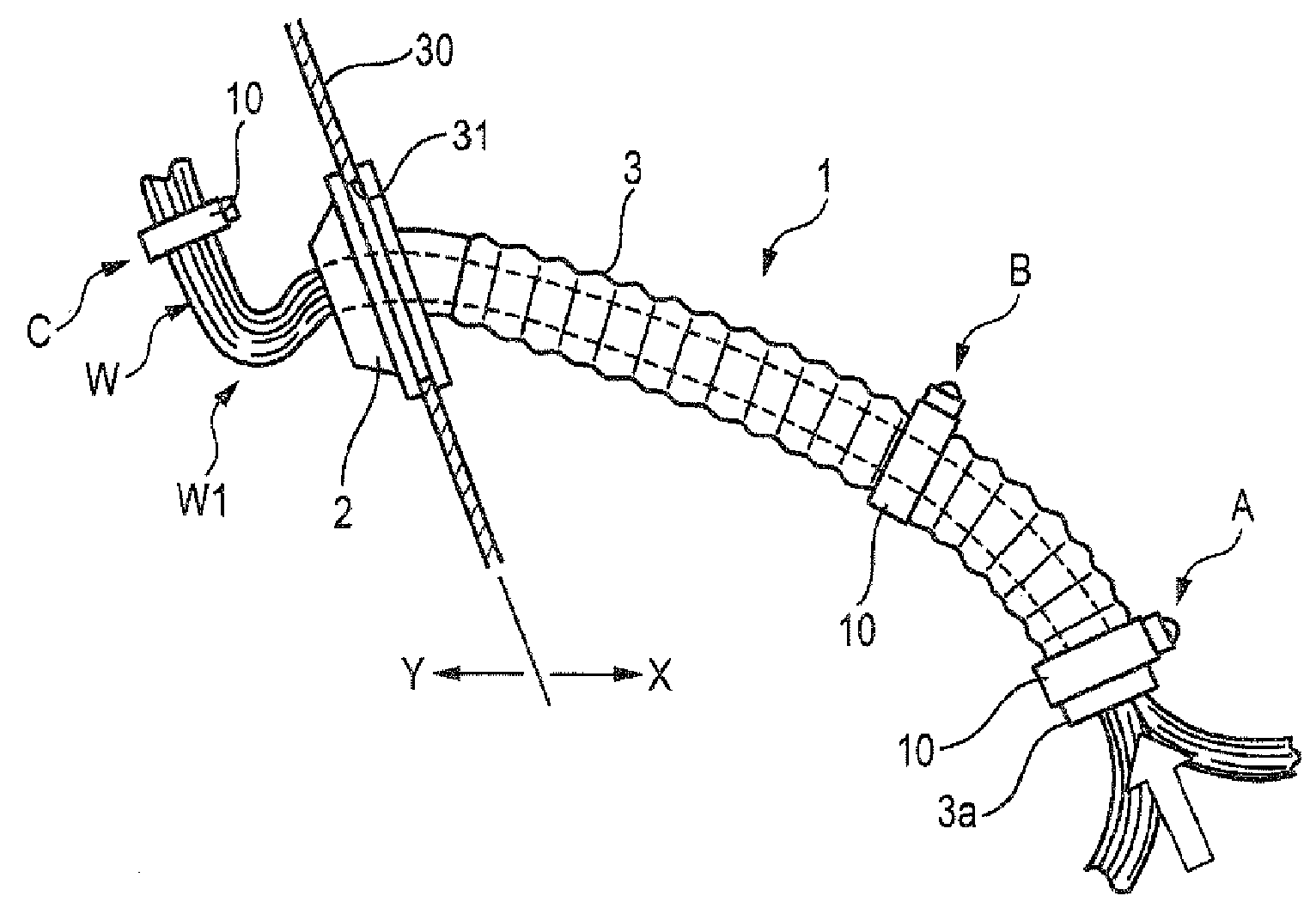
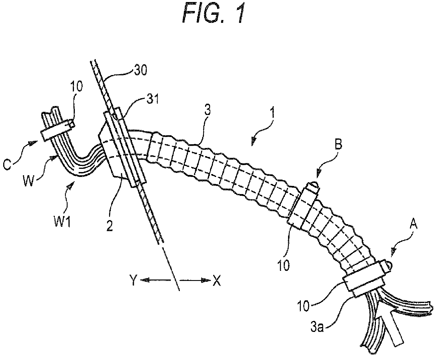
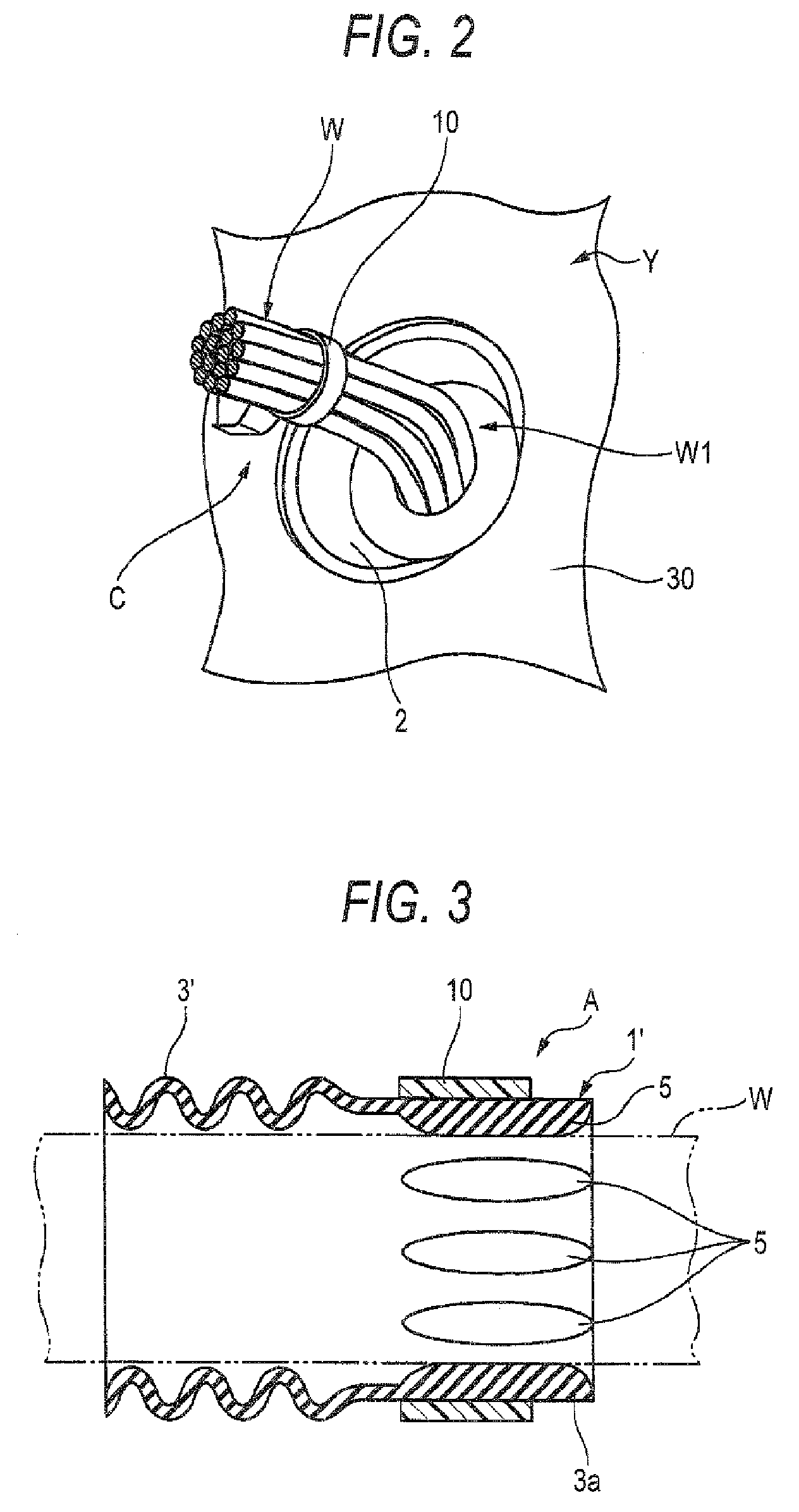
The invention is a wire harness water cut-off structure that aims to provide a simple and cost-effective solution to prevent water from entering the wire harness. The structure includes a long tube that is continuously provided to the main body portion of a grommet, with a narrowed portion in the inner diameter of the tube to cut off water invasion. The narrowed portions can be created by projecting a rib or fastening a strap to the inner or outer periphery of the tube. The front end of the tube can be directed to the lower side to further prevent water invasion. The wire harness water cut-off structure is designed to be efficient in preventing water cut-off without requiring additional labor or time.

Problems solved by technology

However, by simply mounting the grommet with an object of sealing the clearance between an outer periphery of the wire harness and the panel through hole, in a case in which when inside of the engine room is cleaned by high pressure water, water is brought to clearances of wires of the wire harness at inside of the engine room, it cannot be prevented that the water invades the vehicle compartment side by way of the clearances among the wires.
Meanwhile, the grommet 25 of a type of using the seal agent 25 as shown by FIG. 7, poses a problem that time and labor is taken for an operation of filling the seal agent 25, and therefore, it is difficult to promote a productivity.
Further, in the case of the grommet described in Patent Reference 1, the inner portion of the grommet is provided with the means for scattering a wire bundle, and therefore, the structure is complicated and cost is increased.

Method used


Image

  • Wire harness water cut-off structure
  • Wire harness water cut-off structure
  • Wire harness water cut-off structure

Examples


second embodiment

[0050]FIG. 4A is a side view showing a state of attaching a grommet according to a second embodiment, FIG. 4B is a sectional view enlarging Ib portion of FIG. 4A, FIG. 5 is an outlook view showing a portion of a tube of FIG. 4B, FIG. 6 is a perspective view showing a modified example of the portion of the tube of FIG. 5.

[0051]A grommet 101 of the second embodiment includes a grommet main body portion 102 mounted to a through hole 131 of a dash panel 130, and a long tube 103 continuously provided to the grommet main body portion 102. A principal length portion of the tube 103 is provided with a flexibility by thin-walling a peripheral wall thereof and being formed in a shape of a bellows.

[0052]The grommet 101 is fixed to the dash panel 130 by fitting to attach the grommet main body portion 102 to the through hole 131 of the dash panel 130 in a state of penetrating a wire bundle W at an inner portion thereof. Further, the grommet 101 is integrally provided with the long tube 103, and ...


PUM


Abstract

A main body portion of a grommet is mounted to a through hole of a dash panel partitioning an engine room and a vehicle compartment, a long tube is continuously provided to the main body portion, and the tube is arranged at inside of the engine room. A wire harness is inserted to the main body portion and an inner portion of the tube in an unbundled state, under the state, at least two stages of narrowed portions (first, second fixing portions) constituted by narrowing an inner diameter of the tube at a position proximate to a front end of the tube and a position proximate to the main body portion remote from the position. At the narrowed portion, by fastening a strap for fixing to an outer periphery of the tube, the inner diameter of the tube is narrowed. Wires are scattered by providing a bent portion at the wire harness coming out from the grommet.

Description

BACKGROUND OF THE INVENTION[0001]1. Field of the Invention[0002]The present invention relates to a wire harness water cut-off structure for preventing water from invading by way of clearances among wires of the wire harness from a side of an engine room to a side of a vehicle compartment when, for example, the wire harness is wired from the side of the engine room to the side of the vehicle compartment by passing the through hole of a dash panel of an automobile.[0003]2. Related Art[0004]In a background art, when a wire harness is wired between to a side of an engine room and a side of a vehicle compartment by way of a through hole of a dash panel, invasion of water by way of a clearance between the wire harness and the through hole is prevented by arranging a grommet between the wire harness and the through hole.[0005]However, by simply mounting the grommet with an object of sealing the clearance between an outer periphery of the wire harness and the panel through hole, in a case i...

Claims


Application Information

Patent Timeline
Patent Type & Authority Patents(United States)
IPC IPC(8): H01R9/11
CPCB60R16/0222
Inventor KAMENOUE, MASAYOSHIMURAKAMI, TOMOYASUSHISHIDO, HIDETAKA
Owner YAZAKI CORP
Learn More