Method and apparatus for DC integrated current sensor
a current sensor and dc technology, applied in the field of electric power systems, can solve the problems of reducing reliability, reducing reliability, adding extra weight, volume, cost and complexity to the electrical circuit, and heavy/high-cost standalone current sensors and inductors
- Summary
- Abstract
- Description
- Claims
- Application Information
AI Technical Summary
Problems solved by technology
Method used
Image
Examples
second embodiment
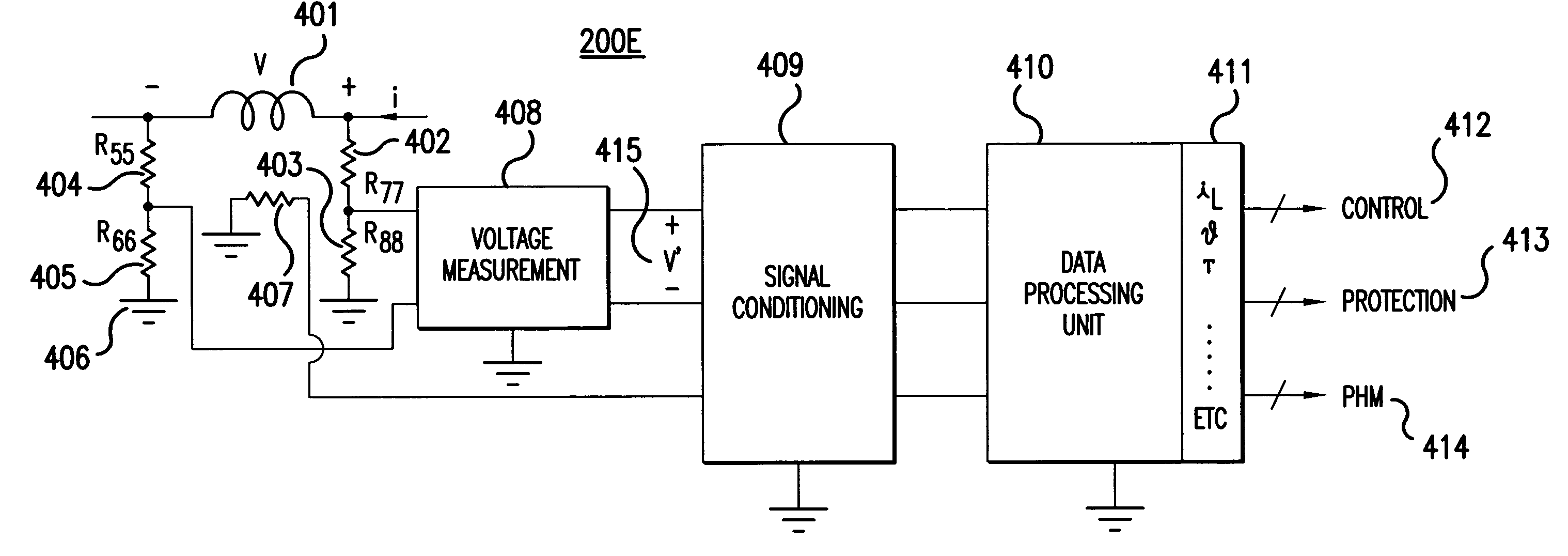
[0046]FIG. 8 illustrates an integrated DC current sensor 200C according to the present invention. FIG. 8 illustrates a preferred embodiment of the present invention for a conceptual circuit implementation of an integrated DC inductor / current sensor.
[0047]The circuit 200C illustrated in FIG. 8 monitors high-side inductor voltage in a safe manner through a resistive network. An instrumentation-amplifier (IN-AMP) 212 is used to ideally detect only the difference in voltage between its input pins. Any common-mode signals (equal potentials for both inputs) such as noise or voltage drops in ground-lines are rejected at the input, without being amplified.
[0048]An AC transformer may pose challenges if used to step-down a DC inductor νL voltage for down-stream low voltage circuitry. A resistive network, such as the one shown in FIG. 8, can be used to step-down the DC inductor voltage for proper operation of down-stream circuits. In an alternative embodiment, an isolation op-amp can be used i...
third embodiment
[0054]FIG. 9A illustrates a transductor circuit used for measuring DC current, for integration into a DC inductor / current sensor according to the present invention. FIGS. 9B, 9C and 9D illustrate transductor properties. FIG. 9A illustrates a circuit arrangement for DC measurement using a transductor and FIG. 9B illustrates an idealized B-H relationship for the transductor. FIG. 9C illustrates flux linkages λ1 for core 1 of the transductor, λ2 for core 2 of the transductor, and λ1+λ2. FIG. 9D illustrates waveforms of source PD, total flux linkage, and current associated with a transductor. Transductors are described in more detail in “Measurement of DC Current”, Section 2.13.3, p. 159, “Electric Machines”, by G. R. Slemon and A. Stranghen, 3rd printing, June 1981, Addison-Wesley Publishing, the entire contents of which are hereby incorporated by reference. According to embodiments of the current invention, a transductor can be integrated in the same DC inductor package to obtain a DC...
fourth embodiment
[0058]FIG. 10 illustrates a common-mode choke used for detecting AC and / or DC current directly, without a need for an integrating circuit, according to the present invention. The common-mode choke illustrated in FIG. 10 includes: a core 371 with an airgap 359; a first winding 361; a second winding 365; input line 351; output line 367; and return lines 369 and 357. The second winding 365 for the common-mode choke is introduced to measure DC or AC current in the same manner as a current transformer. This winding arrangement is advantageous because the inductor and the current transformer share the core and the primary winding. Hence, only one simplified installation and one thermal management system are required for the integrated inductor / current sensor 200D.
[0059]A single phase AC or DC integrated inductor / current sensor 200D is implemented using the terminal voltage of the common-choke inductor. While the integrated DC current sensors described in the previous figures of this appli...
PUM
 Abstract
Description
Claims
Application Information
 - R&D
- Intellectual Property
- Life Sciences
- Materials
- Tech Scout
- Unparalleled Data Quality
- Higher Quality Content
- 60% Fewer Hallucinations
Browse by: Latest US Patents, China's latest patents, Technical Efficacy Thesaurus, Application Domain, Technology Topic, Popular Technical Reports.
© 2025 PatSnap. All rights reserved.Legal|Privacy policy|Modern Slavery Act Transparency Statement|Sitemap|About US| Contact US: help@patsnap.com


