Examination method for CPP-type magnetoresistance effect element having two free layers

a magnetoresistance effect and free layer technology, applied in the field of mr effect element examination method, can solve the problems of inconvenient tmr element, inconvenient dissipation of tmr element, limited reliability of operating current in the conventional structure,

Active Publication Date: 2009-11-10
TDK CORPARATION
View PDF7 Cites 32 Cited by
  • Summary
  • Abstract
  • Description
  • Claims
  • Application Information

AI Technical Summary

Benefits of technology

[0019]In these circumstances, the present invention was made. The object of the present invention is to provide a novel examination method that allows easily examining whether or not the magnetization directions of two free layers have surely been made antiparallel to each other before operating the orthogonalizing bias function part of an element, the orthogonalizing bias function part being disposed in the rear part of the two free layers and having influence over orthogonalizing the magnetization directions of the two free layers.

Problems solved by technology

The problem is that the operating current will be limited in the conventional structure in terms of reliability because the heat dissipating efficiency declines as the area decreases.
However, there is an inconvenience in a TMR element that strong exchange-coupling cannot be produced between two ferromagnetic layers because an insulating layer such as an aluminum oxide (AlOx) film and a magnesium oxide (MgO) film must be placed between the two ferromagnetic layers (free layers) in order to produce the tunnel effect.
As a result, it is extremely difficult to make the magnetization directions of the two ferromagnetic layers (free layers) antiparallel to each other.
However, no proposal has been made for an examination method for assuring that the magnetization directions of two ferromagnetic layers (free layers) are antiparallel to each other in the track width direction.

Method used


Image

  • Examination method for CPP-type magnetoresistance effect element having two free layers
  • Examination method for CPP-type magnetoresistance effect element having two free layers
  • Examination method for CPP-type magnetoresistance effect element having two free layers

Examples


specific experimental embodiment

[0184

[0185]A description of a specific experimental embodiment is given below for the MR element according to the present invention in order to explain the invention in more detail.

[0186]A group of MR elements disposed and formed on a wafer substrate in the matrix state is cut into multiple bars (See Process (III) in FIG. 31).

[0187]An examination is conducted according to the present invention in the cutout bar state for a plurality of specific MR elements selected from a group of MR elements existing in a cutout bar as examination objects.

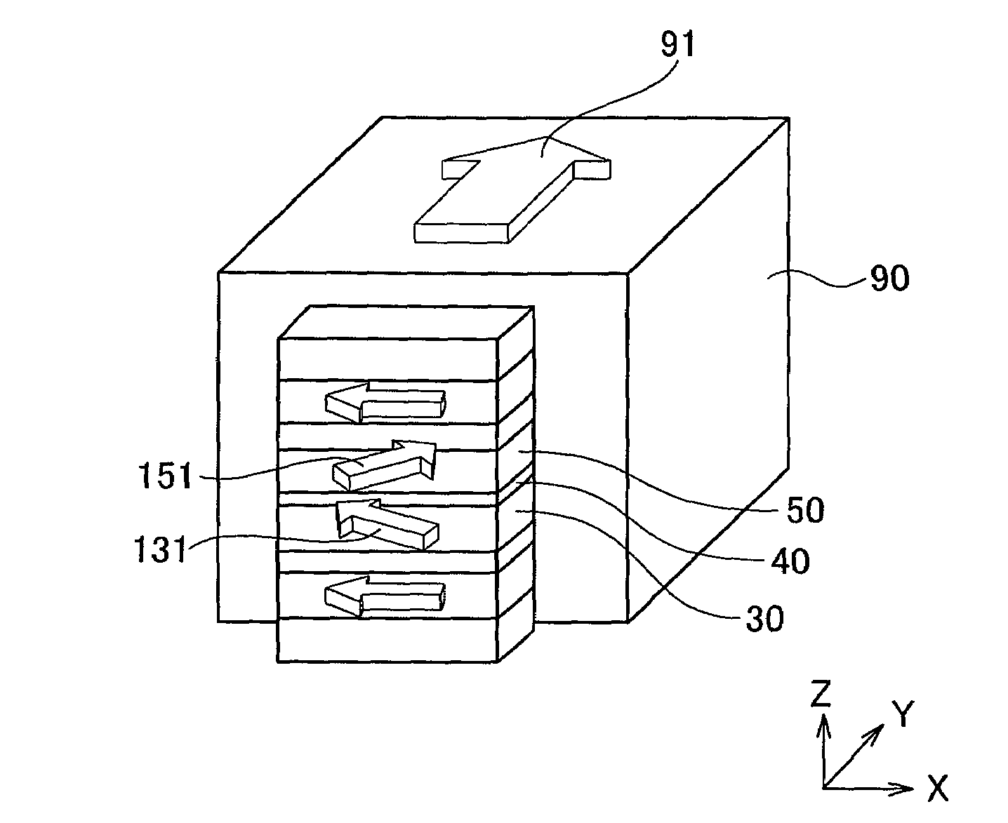
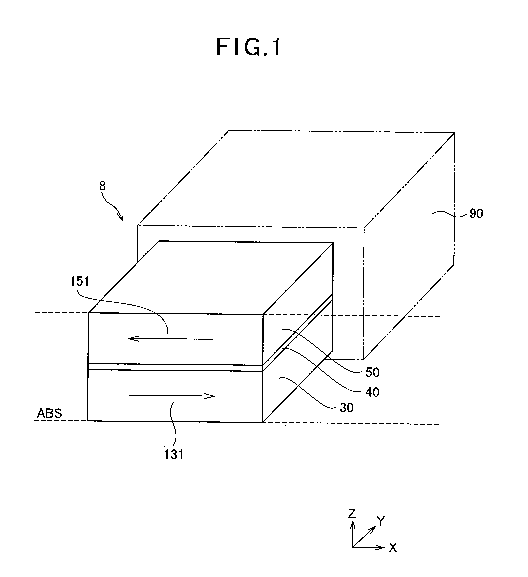
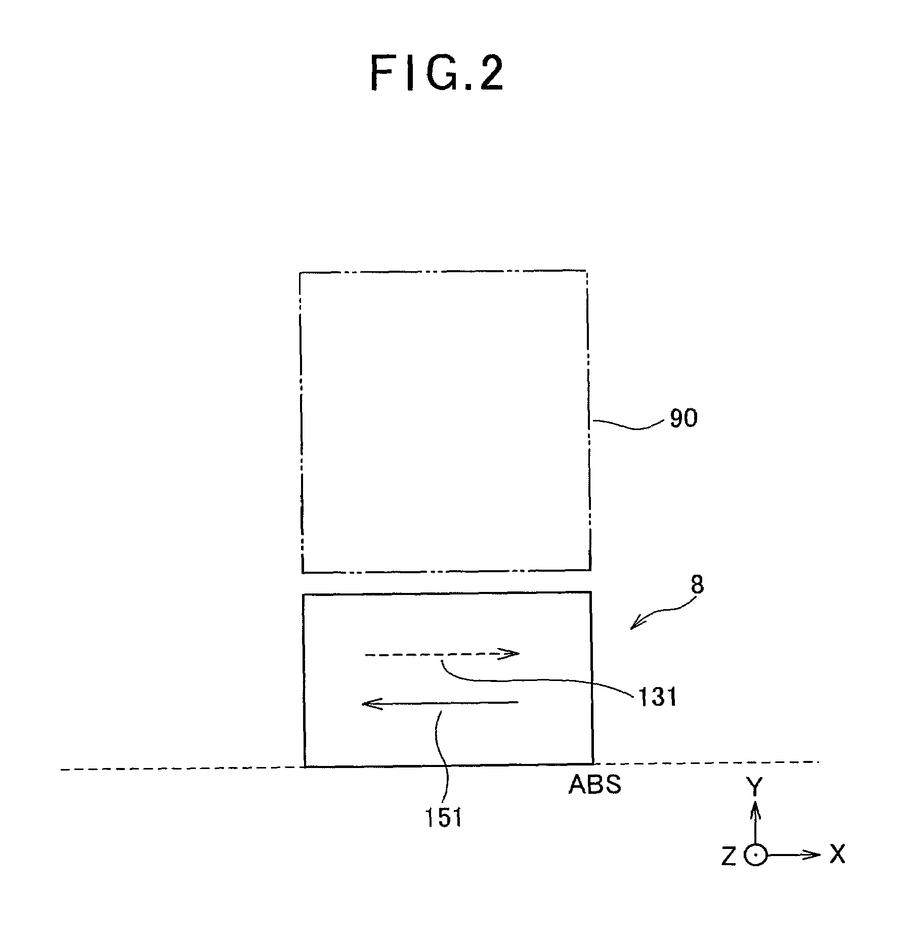
[0188]In other words, the first magnetization forming mode (ABS in magnetization) as shown in FIG. 13 was not carried out for each element in the cutout bar state as shown in Process (III) in FIG. 31, wherein the magnetization direction of the orthogonalizing bias function part 90 is from anterior side of an element (i.e., ABS side) to the posterior side thereof (as shown by the reference numeral 91). Quasi-Static Test (QST) was conducted for a pl...


PUM

PropertyMeasurementUnit
read gap lengthaaaaaaaaaa
total thicknessaaaaaaaaaa

Abstract

An examination method is structured, with respect to a magnetization direction of an orthogonalizing bias function part formed on a posterior part of an magnetoresistance (MR) effect element, of changing the magnetization direction of the orthogonalizing bias function part between a first magnetization forming mode, wherein the magnetization direction is from the anterior side of the element to the posterior side thereof, and a second magnetization forming mode, wherein the magnetization direction is from the posterior side of the element to the anterior side thereof, measuring the output waveform of the element in response to an external magnetic field for each magnetization forming mode and checking the state of the output waveforms of both modes in order to examine whether or not the magnetization directions of the first magnetic layer and the second magnetic layer, both of which functions as free layers, are antiparallel to each other in the track width direction before the orthogonalizing bias function part starts functioning. With the structure, it is realized to easily examine whether or not the magnetization directions of two free layers have surely been made antiparallel to each other before operating the orthogonalizing bias function part of an element.

Description

TECHNICAL FIELD OF THE INVENTION[0001]The present invention relates to an examination method for a CPP type magnetoresistance (MR) effect element having two free layers. Particularly, the present invention relates to an examination method that allows easily examining whether or not the magnetization directions of two free layers have been made antiparallel to each other before operating the orthogonalizing bias function part of an element. The orthogonalizing bias function part is disposed in a rear part of the two free layers and has influence over substantially orthogonalizing the magnetization directions of the two free layers.BACKGROUND OF THE INVENTION[0002]As the recording density of a hard disk drive (HDD) has lately been increasing, there is a need for enhancing the performance of a thin film magnetic head. As a thin film magnetic head, a complex type thin film magnetic head has widely been used that has a laminated structure of a reproducing head having a read-only magnetor...

Claims


Application Information

Patent Timeline
Patent Type & Authority Patents(United States)
IPC IPC(8): G01R33/09G11B5/39
CPCB82Y25/00G01R33/093G01R33/098G11B5/455G11B5/3912Y10T428/1121G11B2005/0016
Inventor MACHITA, TAKAHIKONOGUCHI, KIYOSHIMIYAUCHI, DAISUKE
Owner TDK CORPARATION
Why Eureka
Try Eureka