Magnetic detecting element having free layer formed of NiFe alloy and method of manufacturing the same

a technology of nife alloy and detecting element, which is applied in the field of magnetic detecting element, can solve the problems of low sensitivity, invert the magnetization deterioration of the magnetic characteristics of the free magnetic layer, so as to achieve effective diffusion of the nife alloy layer and the x element layer, and increase the value of ra.

Active Publication Date: 2009-11-10
TDK CORPARATION
View PDF13 Cites 2 Cited by
  • Summary
  • Abstract
  • Description
  • Claims
  • Application Information

AI Technical Summary

Benefits of technology

[0015]The present invention has been finalized with a view to solving the above-mentioned problems, and it is an object of the invention to provide a magnetic detecting element capable of maintaining large ΔRA and of reducing magnetostriction by improving a material forming a free magnetic layer, and a method of manufacturing the same.

Problems solved by technology

However, since the CoFe alloy has higher uniaxial anisotropy and stronger coercive force than an NiFe alloy, the CoFe alloy, which is the main ingredient of the free magnetic layer, makes it difficult to invert the magnetization of the free magnetic layer with an external magnetic field, resulting in low sensitivity.
However, since the copper layer is apt to oxidize, the CoFe alloy formed below the copper layer is also apt to oxidize, which causes serious problems in that the free magnetic layer is demagnetized and magnetic characteristics of the free magnetic layer are deteriorated.
The large magnetostriction causes problems in which a film is distorted and the free magnetic layer is much affected by stress caused by a difference between a thermal expansion coefficient thereof and thermal expansion coefficient of other layers.
However, an object of JP-A-2004-95587 is only to increase the value of ΔRA, but JP-A-2004-95587 does not disclose a structure for maintaining large ΔRA and for reducing magnetostriction when the free magnetic layer is formed of an NiFe alloy.

Method used


Image

  • Magnetic detecting element having free layer formed of NiFe alloy and method of manufacturing the same
  • Magnetic detecting element having free layer formed of NiFe alloy and method of manufacturing the same
  • Magnetic detecting element having free layer formed of NiFe alloy and method of manufacturing the same

Examples


examples

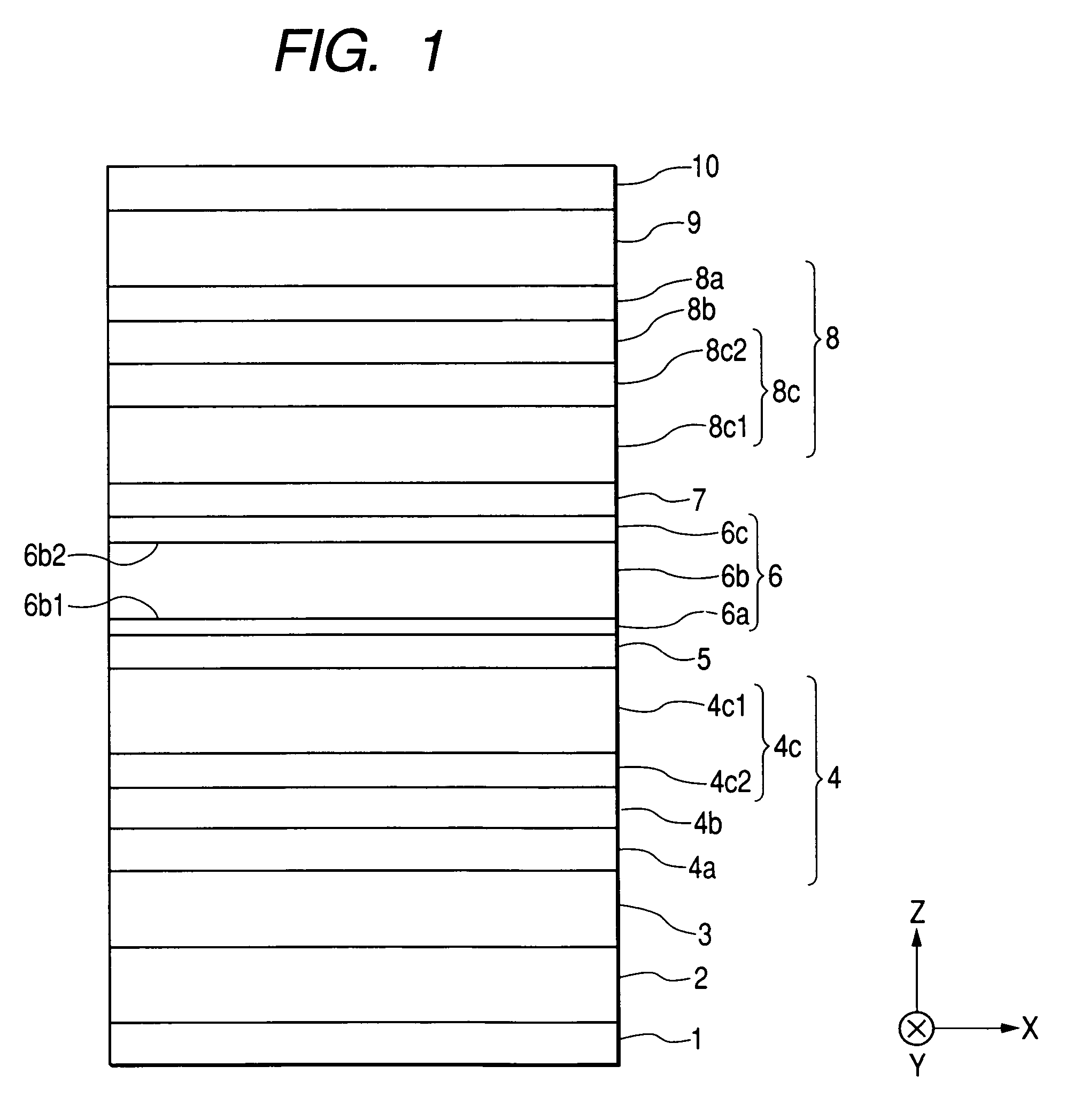
[0105]The dual-spin-value thin film element shown in FIG. 1 is manufactured.

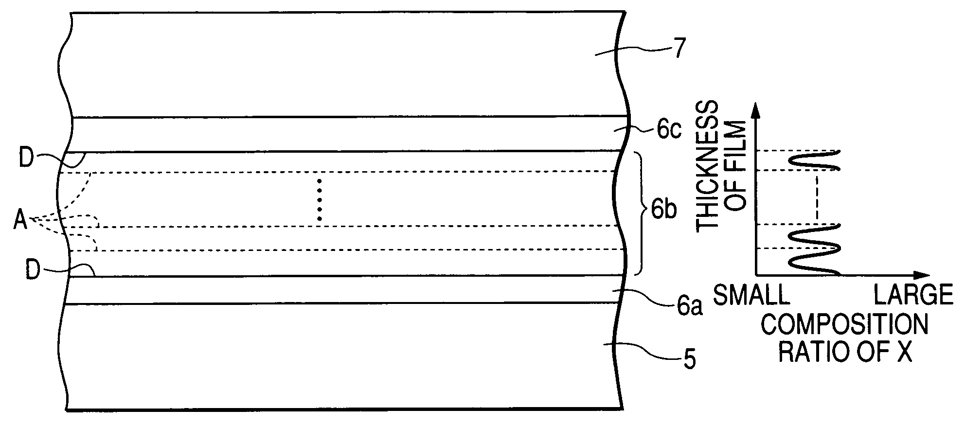
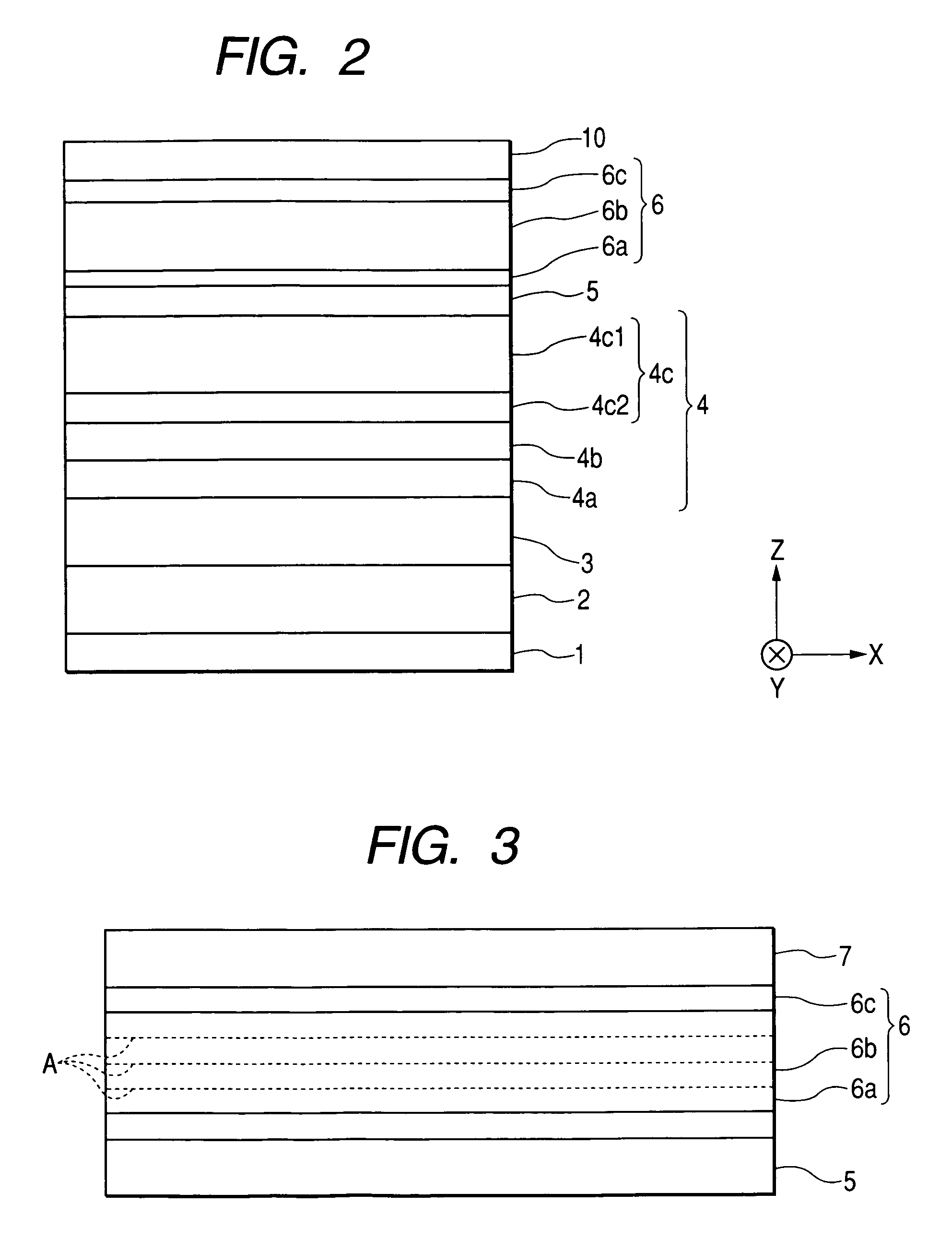
[0106]The basic film structure thereof is as follows: the underlying layer 1; Ta (30) / the seed layer 2; NiFeCr (50) / the lower antiferromagnetic layer 3; IrMn (70) / the lower pinned magnetic layer 4 [the first magnetic layer 4a; FeCo (30) / the non-magnetic intermediate layer 4b; Ru (9.1) / the non-magnetic-intermediate-layer-side magnetic layer 4c2; FeCo (10) / the non-magnetic-layer-side magnetic layer 4c1; CoMnGe (40)] / the non-magnetic layer 5; Cu (43) / the free magnetic layer 6 / the non-magnetic layer 7; Cu (43) / the upper pinned magnetic layer 8 [the non-magnetic-layer-side magnetic layer 8c1; CoMnGe (40) / the non-magnetic-intermediate-layer-side magnetic layer 8c2; FeCo (10) / the non-magnetic intermediate layer 8b; Ru (9.1) / the first pinned magnetic layer 8a; FeCo (30)] / the upper antiferromagnetic layer 9; IrMn (70) / the protective layer 10; Ta (200). Here, the parenthesized numerical values indicate thicknesses, an...


PUM

PropertyMeasurementUnit
magneticaaaaaaaaaa
magnetizationaaaaaaaaaa
composition ratioaaaaaaaaaa

Abstract

There are provided a magnetic detecting element capable of maintaining large ΔRA and of reducing magnetostriction by improving a material forming a free magnetic layer, and a method of manufacturing the same. An NiFeX alloy layer is formed in a free magnetic layer. For example, the element X is Cu. The NiFeX alloy layer formed in the free magnetic layer makes it possible to maintain large ΔRA and to more reduce the magnetostriction of the free magnetic layer, compared with a structure in which an NiFe alloy layer is formed in the free magnetic layer.

Description

BACKGROUND OF THE INVENTION[0001]1. Field of the Invention[0002]The present invention relates to a magnetic detecting element including a pinned magnetic layer whose magnetization direction is fixed and a free magnetic layer which is formed on the pinned magnetic layer with a non-magnetic layer interposed therebetween and whose magnetization direction varies in accordance with an external magnetic field. In particular, the invention relates to a magnetic detecting element capable of maintaining large ΔRA, which is the product of a magnetoresistance variation ΔR and an element area A, and of reducing magnetostriction, and a method of manufacturing the same.[0003]2. Description of the Related Art[0004]A magnetic detecting element having a multi-layer film of a free magnetic layer, a non-magnetic layer, and a pinned magnetic layer is classified into a CIP (current in the plane) type or a CPP (current perpendicular to the plane) type, according to a direction in which a current flows th...

Claims


Application Information

Patent Timeline
Patent Type & Authority Patents(United States)
IPC IPC(8): G11B5/39
CPCB82Y25/00B82Y40/00G01R33/093G11B5/3903H01F10/14H01F10/3263H01F41/302H01L43/10Y10T29/49044H01F10/3277H01F10/1936H10N50/85
Inventor ISHIZONE, MASAHIKOIDE, YOSUKESAITO, MASAMICHIHASEGAWA, NAOYA
Owner TDK CORPARATION
Why Eureka
Try Eureka