Tunneling magnetic sensing element and method for manufacturing the same

Inactive Publication Date: 2008-07-03
TDK CORPARATION
View PDF2 Cites 1 Cited by
  • Summary
  • Abstract
  • Description
  • Claims
  • Application Information

AI Technical Summary

Benefits of technology

[0025]In the tunneling magnetic sensing element of the present invention, it is believed that it is possible to prevent the element of a layer formed on the first protective layer composed of Pt from easily diffusing into the free magnetic layer and the insulating barrier layer, an

Problems solved by technology

However, when heat treatment is performed, Ta diffuses into the free magnetic layer or induces interfacial strain and interfacial stress with respect to the free magnetic layer, resulting in an increase in the magnetostric

Method used


Image

  • Tunneling magnetic sensing element and method for manufacturing the same
  • Tunneling magnetic sensing element and method for manufacturing the same
  • Tunneling magnetic sensing element and method for manufacturing the same

Examples


Example

EXAMPLE 1

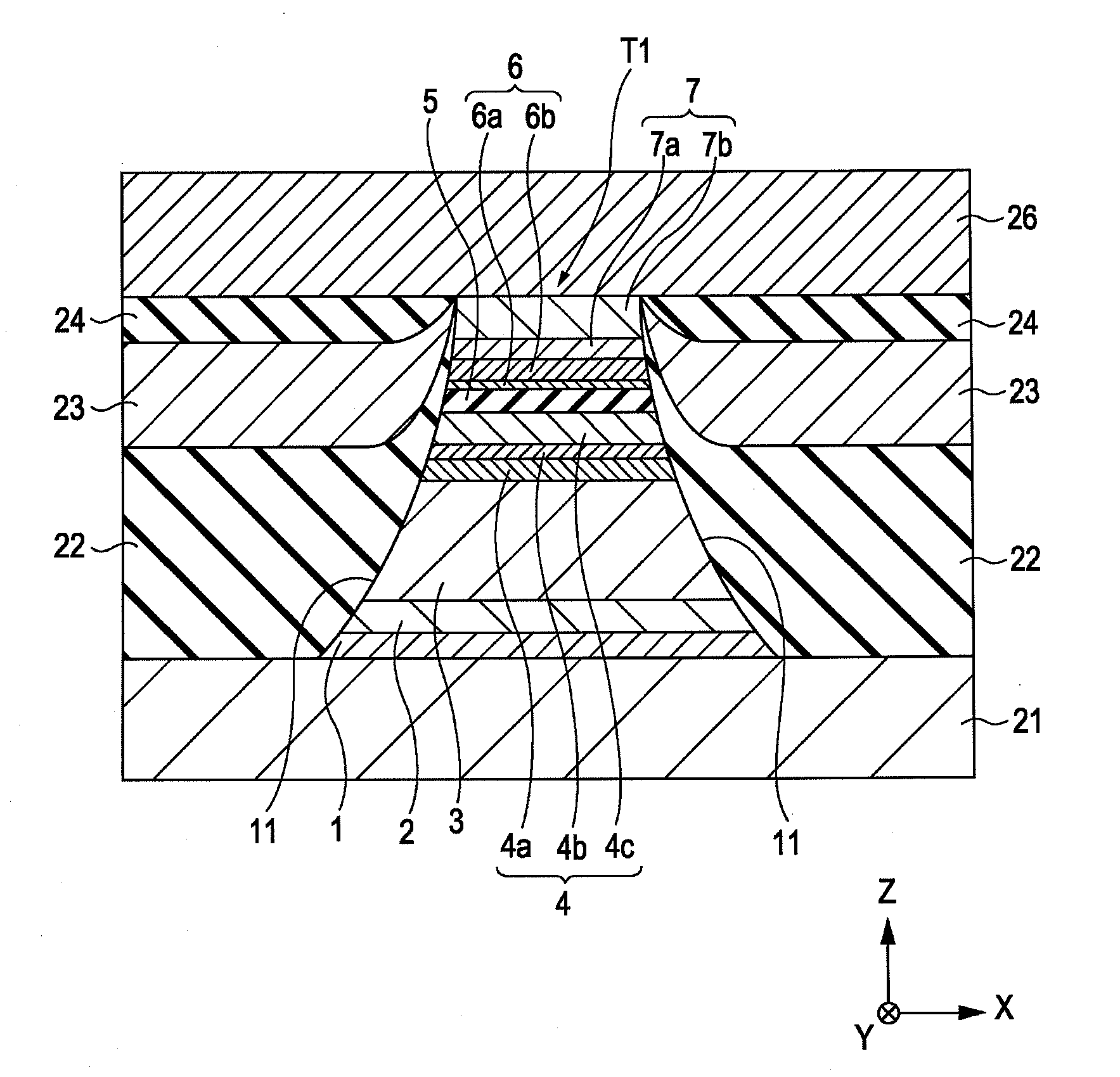
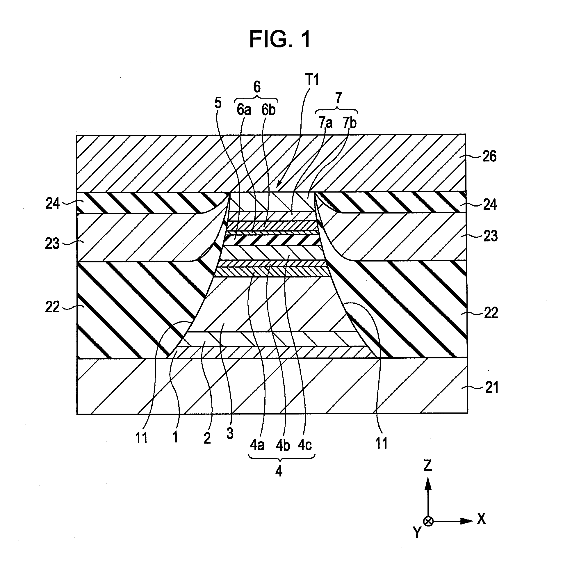
[0079]A tunneling magnetic sensing element shown in FIG. 1 was fabricated. A laminate T1 was formed by depositing, from the bottom, underlying layer 1;Ta(80) / seed layer 2;Ni49at %Fe12at %Cr39at %(50) / antiferromagnetic layer 3;Ir26at %Mn74at %(70) / pinned magnetic layer 4 [first pinned magnetic sublayer 4a;Co70at %Fe30at %(14) / nonmagnetic intermediate sublayer 4b;Ru(9.1) / second pinned magnetic sublayer 4c;Co40at %Fe40at %B20at %(18)] / insulating barrier layer 5;MgO(12) / free magnetic layer 6 [enhancement layer 6a;Co50at %Fe50at %(10) / soft magnetic layer 6b;Ni86at %Fe14at %(50)] / protective layer 7 [first protective layer;Pt(20) / second protective layer;Ta(180)]. A numerical value in parentheses indicates the average thickness of each layer in unit of angstrom (Å). After the laminate T1 was formed, annealing treatment was carried out at 270° C. for 3 hours 30 minutes.

[0080]A tunneling magnetic sensing element was fabricated as in Example 1 except that, without forming a first prot...

Example

EXAMPLE 2

[0086]A tunneling magnetic sensing element was fabricated as in Example 1 except that the insulating barrier layer 5 was formed using Al—O. An Al layer was formed by sputtering with a thickness of 3 Å on the second pinned magnetic sublayer 4c, followed by oxidation. Thereby, the insulating barrier layer composed of Al—O was obtained.

[0087]A tunneling magnetic sensing element was fabricated as in Example 2 except that, without forming a first protective layer 7a, the protective layer 7 was formed so as to include one layer of Ta (200 Å) (Comparative Example 2).

Example

EXAMPLE 3

[0088]A tunneling magnetic sensing element was fabricated as in Example 1 except that the insulating barrier layer 5 was formed using Ti—O. A Ti layer was formed by sputtering with a thickness of 6 Å on the second pinned magnetic sublayer 4c, followed by oxidation. Thereby, the insulating barrier layer composed of Ti—O was obtained.

[0089]A tunneling magnetic sensing element was fabricated as in Example 3 except that, without forming a first protective layer 7a, the protective layer 7 was formed so as to include one layer of Ta (200 Å) (Comparative Example 3).

[0090]With respect to each of Examples 2 and 3 and Comparative Examples 2 and 3, the magnetostriction λ of the free magnetic layer was measured, and the results thereof are shown in Table 2 below together with the values of Example 1 and Comparative Example 1.

TABLE 2Protective layerSecondInsulating barrier layerFirst protectiveprotective layerMg—OAl—OTi—Olayer (thickness)(thickness)Magnetostriction (ppm)Pt (20 Å)Ta (180...


PUM

PropertyMeasurementUnit
Volumeaaaaaaaaaa
Volumeaaaaaaaaaa
Fractionaaaaaaaaaa

Abstract

A tunneling magnetic sensing element includes a pinned magnetic layer whose magnetization direction is pinned in one direction, an insulating barrier layer disposed on the pinned magnetic layer, a free magnetic layer whose magnetization direction varies in response to an external magnetic field disposed on the insulating barrier layer, and a first protective layer composed of platinum (Pt) disposed on the free magnetic layer. Consequently, it is possible to greatly decrease the magnetostriction of the free magnetic layer while maintaining a high rate of change in resistance compared with a tunneling magnetic sensing element which is not provided with a first protective layer.

Description

CLAIM OF PRIORITY[0001]This application claims benefit of the Japanese Patent Application No. 2006-355084 filed on Dec. 28, 2006, the entire content of which is hereby incorporated by reference.BACKGROUND[0002]1. Field of the Invention[0003]The present invention relates to magnetic sensing elements which utilize a tunneling effect and which are to be mounted on magnetic reproducing devices, such as hard disk drives, or other magnetic sensing devices. More particularly, the invention relates to a tunneling magnetic sensing element which includes a free magnetic layer having low magnetostriction λ and which has a high rate of change in resistance (ΔR / R), the element thus having excellent magnetic sensitivity and stability, and a method for manufacturing the same.[0004]2. Description of the Related Art[0005]In a tunneling magnetic sensing element (tunneling magnetoresistance element), the change in resistance is caused by a tunneling effect. When the magnetization direction of a pinned...

Claims


Application Information

Patent Timeline
IPC IPC(8): H01F1/00H01F41/14
CPCB82Y10/00H01F10/3295B82Y40/00G01R33/093G01R33/098G11B5/3906G11B5/3909G11B5/40H01F10/3254H01F10/3272H01F41/302H01F41/32H01L43/08H01L43/12B82Y25/00Y10T428/31678H10N50/01H10N50/10
Inventor NISHIMURA, KAZUMASANAKABAYASHI, RYOHASEGAWA, NAOYASAITO, MASAMICHIIDE, YOSUKEISHIZONE, MASAHIKO
Owner TDK CORPARATION
Why Eureka
Try Eureka