Electrical distribution panel for a number of critical and non-critical loads

a technology for distribution panels and critical loads, applied in the direction of substation/switching arrangement casings, transportation and packaging, emergency power supply arrangements, etc., can solve the problems of requiring significant time and effort to rewire a load center in order and a backup power sour

Inactive Publication Date: 2009-11-10
EATON CORP
View PDF9 Cites 33 Cited by
  • Summary
  • Abstract
  • Description
  • Claims
  • Application Information

AI Technical Summary

Problems solved by technology

Today, it requires significant time and effort to rewire a load center in order to connect a backup power source, such as an electric generator or other auxiliary power unit (APU) (e.g., a device whose purpose is to provide electrical energy), to critical circuits in, for example, residential and relatively smaller scale commercial structures.

Method used


Image

  • Electrical distribution panel for a number of critical and non-critical loads
  • Electrical distribution panel for a number of critical and non-critical loads
  • Electrical distribution panel for a number of critical and non-critical loads

Examples


Embodiment Construction

[0026]As employed herein, the term “number” shall mean one or an integer greater than one (i.e., a plurality).

[0027]As employed herein, the term “electrical distribution panel” includes load centers, panelboards, and other indoor or outdoor panels for distributing electrical power to a number of electrical loads.

[0028]The invention will initially be described as applied to miniature single pole circuit breakers, although it will become apparent that it could also be applied to other types of circuit breakers, such as circuit breakers having two, three, four or more poles.

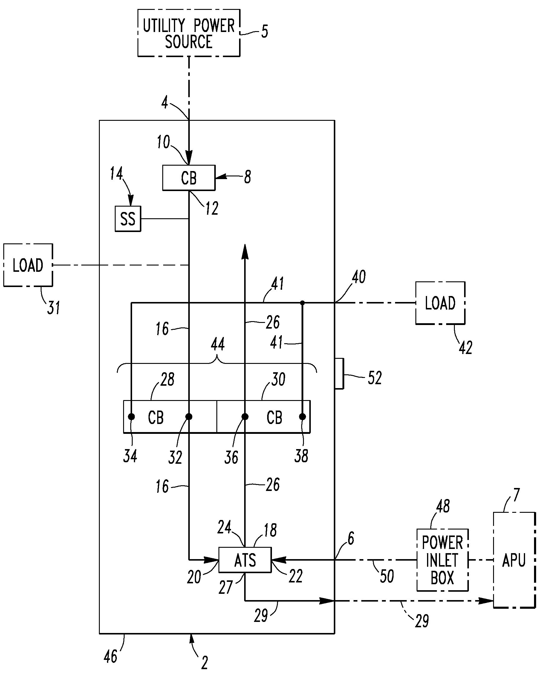
[0029]Referring to FIG. 1, an electrical distribution panel, such as the example load center 2, includes a first power input 4, a second power input 6, a first circuit breaker (CB) 8 including a first terminal, such as the example line terminal 10, electrically connected to the first power input 4 and a second terminal, such as the example load terminal 12. For instance, the example first CB 8 is a main circuit brea...


PUM


Abstract

An electrical distribution panel includes first and second power inputs, a first circuit breaker electrically between the first power input and a first load bus, a second load bus, an automatic transfer switch having a first input electrically connected to the first load bus, a second input electrically connected to the second power input, and an output electrically connected to the second load bus. The transfer switch selectively electrically connects one of the first and second inputs to the output thereof. Pairs of circuit breakers each includes a second breaker having a first terminal electrically connected to the first load bus, and a second terminal, a third breaker including a first terminal electrically connected to the second load bus, and a second terminal, a power output electrically connected to the second terminals, and an interlock cooperating with the circuit breaker pair to prevent both of them from being closed simultaneously.

Description

BACKGROUND OF THE INVENTION[0001]1. Field of the Invention[0002]This invention pertains generally to electrical distribution panels and, more particularly, to electrical distribution panels accommodating non-critical loads and critical loads being supplied with power from a backup power source in response to power from a primary power source becoming unacceptable.[0003]2. Background Information[0004]Electrical distribution panels, such as load centers, incorporate a plurality of circuit breakers and provide a safe and controllable distribution of electric power. Such load centers have become a common feature in both residential and commercial structures.[0005]A known proposal for either new construction or the retrofit of existing installations involves the addition of a separate load center panel for critical circuits. This separate load center panel receives a backup power source and, also, manually switches between a utility power source and the backup power source. This can be u...

Claims


Application Information

Patent Timeline
Patent Type & Authority Patents(United States)
IPC IPC(8): H02B1/04H01H9/20H02J9/00
CPCH02J9/06
Inventor LUEBKE, CHARLES J.JUDS, MARK A.
Owner EATON CORP
Why Eureka
Try Eureka