Floor panel

a technology for floor panels and soffits, applied in the field of floor panels, can solve the problem of a certain amount of prestressing on the second side edge of the lock

Active Publication Date: 2009-11-17
VÄLINGE INNOVATION AB
View PDF489 Cites 211 Cited by
  • Summary
  • Abstract
  • Description
  • Claims
  • Application Information

AI Technical Summary

Benefits of technology

[0008]A development of the invention provides that the radius of curvature of the contour of the underside of the tongue remains essentially constant over at least 90°, with the result that a uniform pivoting-in movement and a straightforward sliding action on the corresponding recess can take place.
[0009]A development provides that a step-like milled relief with a shoulder which projects in the direction of the underside is formed on the second side edge, the shoulder having an essentiall...

Problems solved by technology

The channel, furthermore, gives rise to a slight spring effect, with the result th...

Method used


Image

  • Floor panel
  • Floor panel
  • Floor panel

Examples


Embodiment Construction

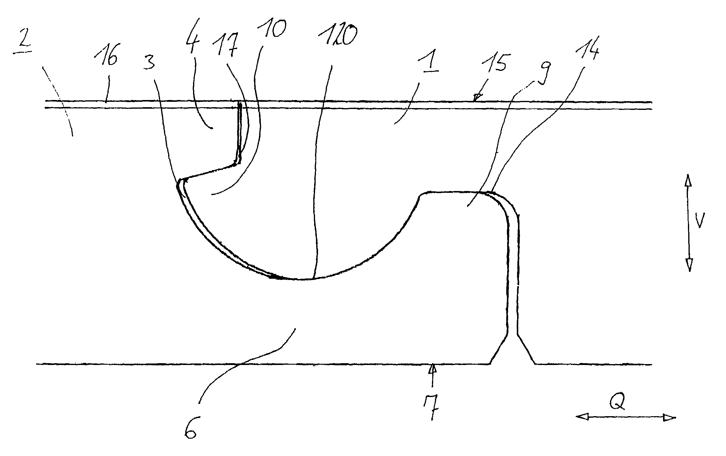
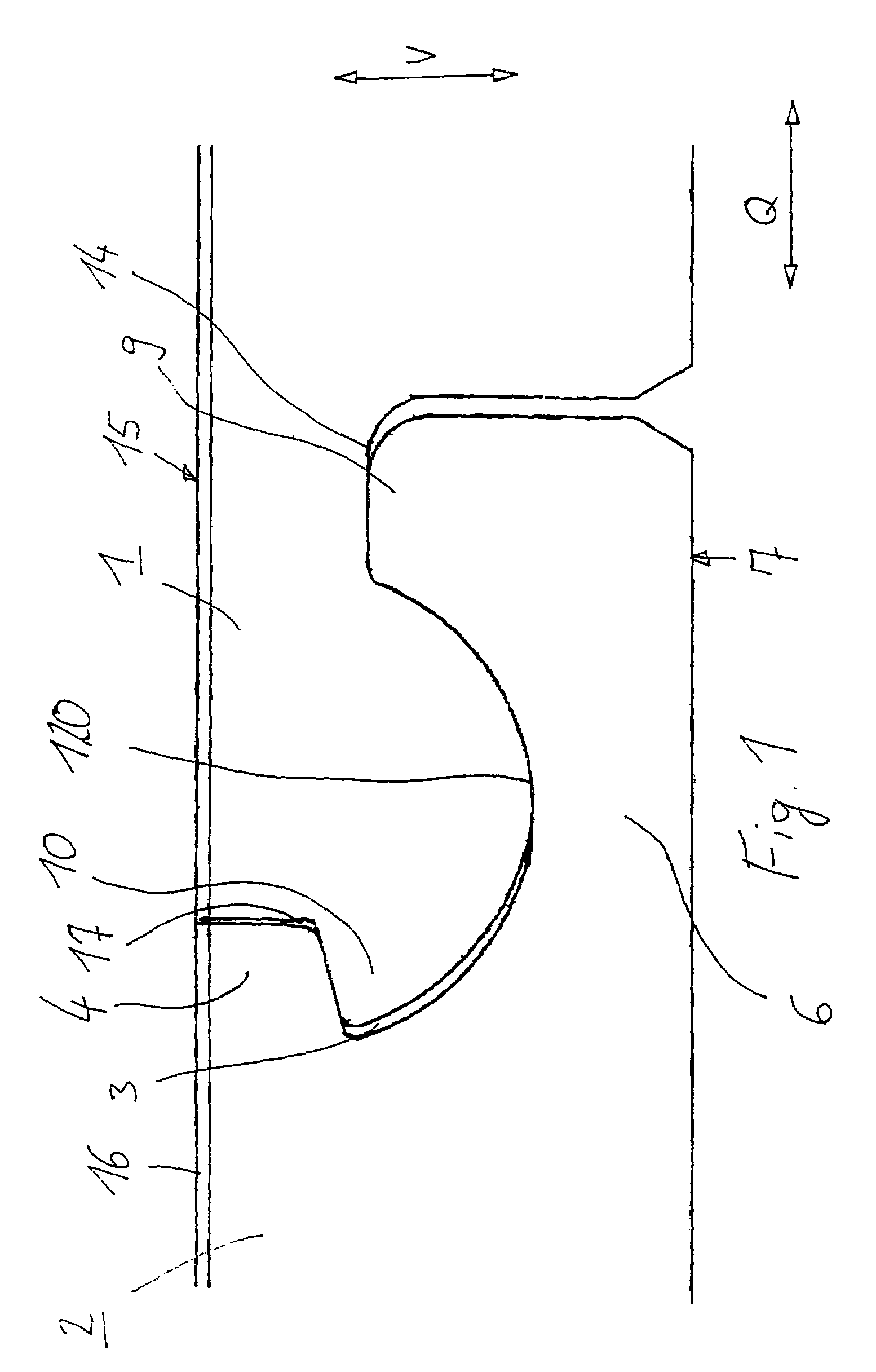
[0014]FIG. 1 shows a floor panel 1 which comprises a medium-density or high-density fiberboard (MDF or HDF), which is locked with a second floor panel 2. On their top side 15, the floor panels 1, 2 are provided with a decorative layer 16 which may be formed, for example, by a paper layer which exhibits a woodgrain and is coated with a synthetic-resin layer serving to protect against wear. A sound-insulation layer may be adhesively bonded to the underside in order to improve the footfall-sound properties of the laid floor panels 1, 2. As an alternative to using an HDF or MDF board, the panel may be produced from an OSB material.

[0015]The panel 1 is provided with a tongue 10 on a first side edge, preferably on the longitudinal side of the panel, and with a correspondingly designed groove 3 on the opposite side. The groove 3 and the tongue 10 run over the entire length of the side edge. Provided on the tongue 10 is an outwardly projecting, rounded nose, which is adjoined by the undersi...


PUM


Abstract

Floor panel which is bounded in a horizontal plane by a top side, which is provided with a decorative layer or the like, and an underside, which is provided for bearing on an underlying surface, the floor panel being provided with means for the releasable connection of at least two panels, it being the case that the connecting means are formed on at least one first side edge such that locking takes place in the transverse direction (Q) and vertical direction (V), that form-fitting elements for locking in the vertical direction (V) with a further panel are formed on a second side edge, which runs at an angle to the first side edge, that the form-fitting elements are spaced apart from one another in the transverse direction (Q) and in the vertical direction (V) on two spaced-apart, essentially vertically oriented walls, in which case a tongue is formed on the first side edge, the tongue extending in the longitudinal direction of the side edge, and a recess, corresponding to the tongue, is formed on an opposite side edge, the underside of the tongue, starting from the tip of the tongue, having a continuously curved contour.

Description

BACKGROUND OF THE INVENTION[0001]1. Field of the Invention[0002]The invention relates to a floor panel.[0003]2. Background Description[0004]WO 01 / 75247 A1 discloses a floor panel which, on a first side edge, has connecting means for locking in the transverse and vertical directions. These locking means are arranged on the longitudinal side of the panel and bring about locking by the connecting means being introduced and pivoted into a corresponding recess of a second panel. The transverse side of the panel has two snap-in hooks which, when the panels are laid, are intended to engage in corresponding undercuts of an adjacent panel and to hinder the vertical movement between the laid panels. The two snap-in hooks are located vertically one above the other.[0005]The disadvantage with such a profile is the fact that such a profile configuration does not ensure that the panels are securely locked with one another since the snap-in hooks, which are arranged one above the other, are presse...

Claims


Application Information

Patent Timeline
IPC IPC(8): E04B2/00E04F15/02
CPCE04F15/02E04F2201/0153E04F2201/05E04F2201/026E04F2201/023
Inventor GRAFENAUER, THOMAS
Owner VÄLINGE INNOVATION AB
Why Eureka
Try Eureka