Post-tension pile anchor foundation and method therefor

a technology of post-tension and pile anchors, which is applied in the direction of buildings, buildings, constructions, etc., to achieve the effects of easy and fast re-leveling, increased or decreased number of pile anchors, and greater flexibility in design

Inactive Publication Date: 2009-11-17
TERRACON CONSULTANTS INC
View PDF50 Cites 88 Cited by
  • Summary
  • Abstract
  • Description
  • Claims
  • Application Information

AI Technical Summary

Benefits of technology

[0015]Another object of the present invention is to provide a pile anchor foundation in accordance with the preceding object which includes a concrete cap positioned above the pile anchors and which allows the pile anchors to be pulled upwardly and the foundation cap pulled downwardly to develop soil resistance for both of the post-tensioned elements.
[0025]A final object of the present invention to be set forth herein is to provide a post-tensioned pile anchor foundation and method for construction which may be utilized in a wide range of soils from water-laden sand or clay formations to solid rock, may be formed in situ in remote locations, and will incorporate a minimum amount of concrete or other cementious materials, while providing at the same time a concrete foundation which can be maintained under heavy post-tension forces.

Problems solved by technology

However, the concrete foundations of my aforesaid patents do not relate to pile anchor foundations.

Method used


Image

  • Post-tension pile anchor foundation and method therefor
  • Post-tension pile anchor foundation and method therefor
  • Post-tension pile anchor foundation and method therefor

Examples


Embodiment Construction

[0039]In describing a preferred embodiment of the invention illustrated in the drawings, specific terminology will be resorted to for the sake of clarity. However, the invention is not intended to be limited to the specific terms so selected, and it is to be understood that each specific term includes all technical equivalents which operate in a similar manner to accomplish a similar purpose.

[0040]One embodiment of a pile anchor foundation according to the present invention is shown in the '281 application using corrugated metal pipes to define the perimeter wall of the anchor piles. It has been found that the pile anchors can be formed in various other ways known to those skilled in the art in order to form a post-tensioned foundation according to the present invention. Such further embodiments are illustrated and described herein.

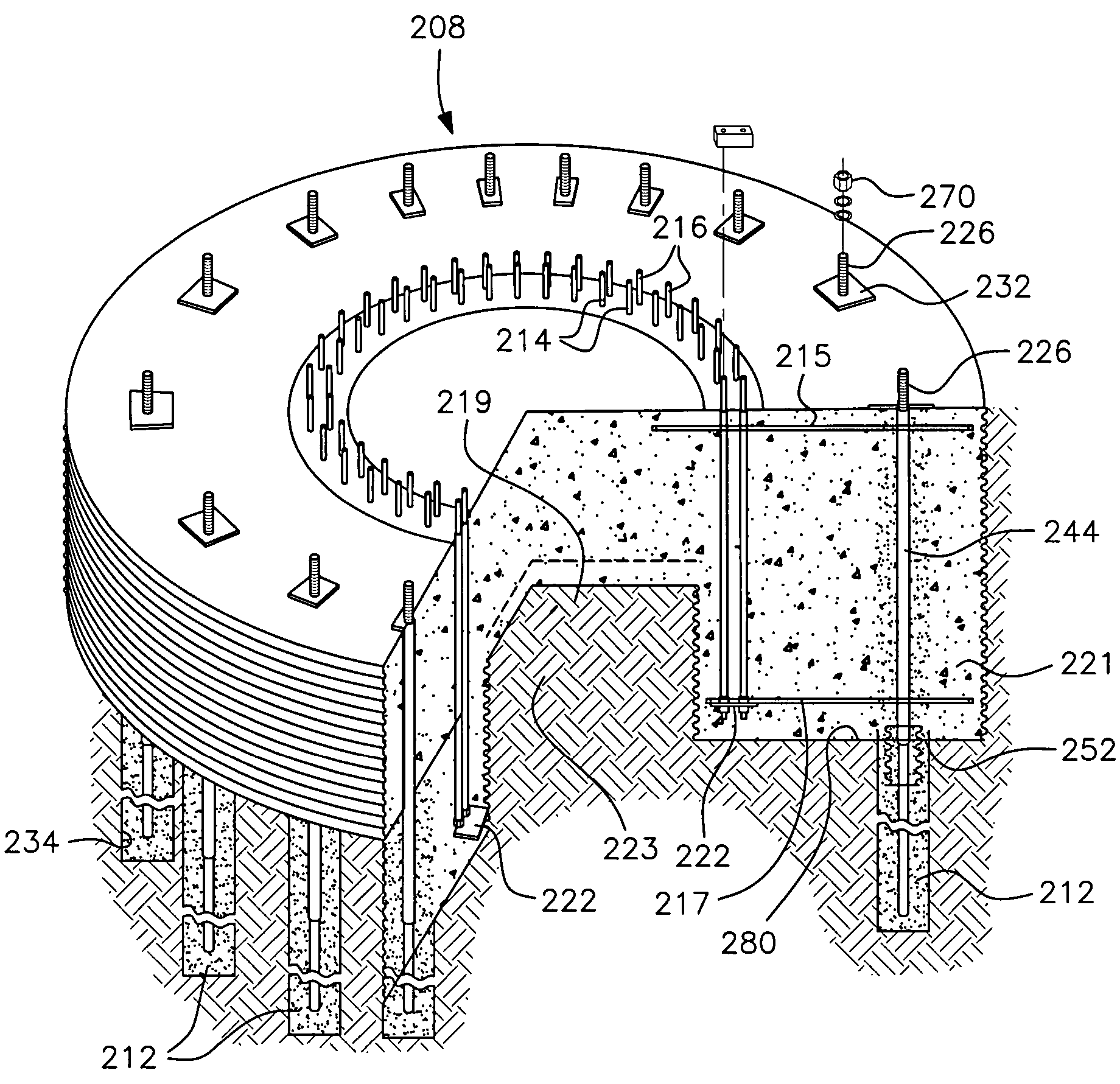
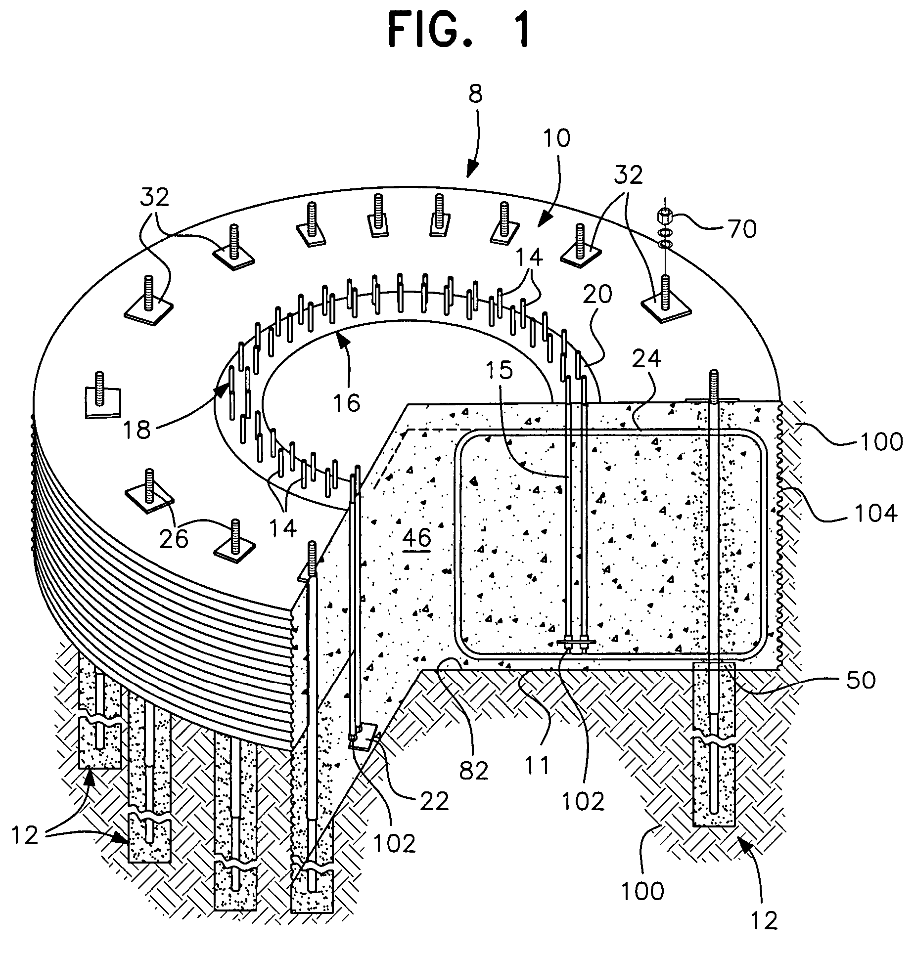
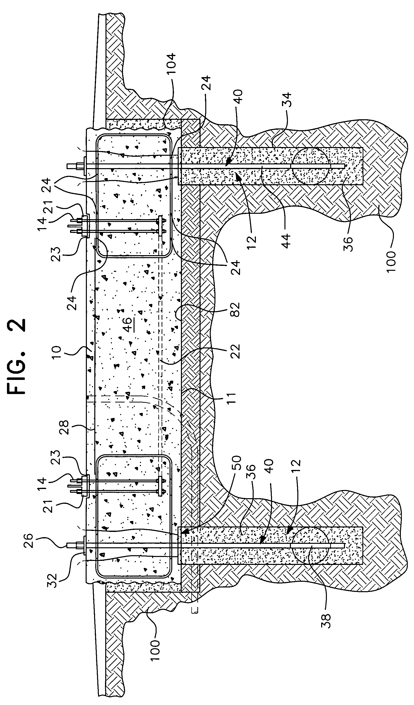
[0041]As shown in FIGS. 1-3, another post-tensioned pile anchor foundation of the present invention, generally designated by reference numeral 8, has a c...


PUM


Abstract

A post-tensioned pile anchor foundation and method therefor creates a void or highly compressible region between a drilled or driven pile anchor surrounding a post-tensioned anchor bolt or tendon and the bottom of a foundation cap. The void or compressible region can be formed by compressible spacers or void forming elements placed between the top of the pile anchor and the concrete cap. As the anchor bolt or tendon is post-tensioned against the cap, the void forming element is compressed or crushed, allowing the cap to be pulled downwardly and the pile anchor to be pulled upwardly toward the cap against the resistance of the surrounding soil.

Description

[0001]This application claims the benefit of priority to U.S. Provisional Patent Application No. 60 / 797,746 filed May 5, 2006, and is a continuation-in-part of copending U.S. application Ser. No. 10 / 734,281, filed Dec. 15, 2003, the subject matter of which is expressly incorporated herein by reference as if fully set forth in its entirety (hereinafter referred to as the '281 application”).BACKGROUND OF THE INVENTION[0002]1. Field of the Invention[0003]The present invention is related to the field of pile anchor foundations and, more particularly, to a post-tensioned pile anchor foundation including a post-tensioned foundation cap and a plurality of post-tensioned pile anchors extending vertically downward therefrom and a method of constructing such a post-tensioned pile anchor foundation.[0004]2. Description of the Related Art[0005]In a normal pile foundation, the piles extend to or into the above concrete foundation and are only compression resisting foundation extensions. Such pil...

Claims


Application Information

Patent Timeline
Patent Type & Authority Patents(United States)
IPC IPC(8): E02D27/00
CPCE04H12/085E02D27/12
Inventor HENDERSON, ALLAN P.
Owner TERRACON CONSULTANTS INC
Why Eureka
Try Eureka