Vented socket

a technology of vented sockets and lamp housings, which is applied in the direction of connection contact materials, coupling device connections, lighting and heating apparatuses, etc., can solve the problems of inconvenient fully automated manufacturing processes, prior art techniques are susceptible to abrasion damage, and the manufacturing step of forming the hole in the lamp housing is a time-consuming and expensive operation, so as to improve moisture evacuation, reduce cost and effort, and improve the effect of moisture evacuation

Active Publication Date: 2009-11-17
TENNECO INC
View PDF19 Cites 8 Cited by
  • Summary
  • Abstract
  • Description
  • Claims
  • Application Information

AI Technical Summary

Benefits of technology

[0011]The assembly and method according to this invention are particularly conducive to fully automated manufacturing processes which result in product being manufactured at minimal cost and effort. The internally applied vent patch is far less susceptible to abrasive damage, and therefore functions as intended over a generally longer service life than do comparable prior art examples. Furthermore, the subject technique has shown better moisture evacuation over prior art venting methods. The invention eliminates the need to design a venting system within the lamp construction, as taught by many prior art systems. Rather, the vent system is incorporated into the socket feature, thus making the design and construction of the lamp housing less costly. By eliminating the hole through the housing, as taught by prior art designs, a potential visual impact is also avoided. Likewise, there is no need to employ camouflaging features that hide unsightly vent patch.

Problems solved by technology

The hole is sometimes left open, but there is concern with dirt and excessive water intrusion such that manufacturers often cover the vent hole to prevent dirt and water from entering the lamp enclosure.
However, exposed hydrophobic vents are susceptible to damage affecting performance.
Also, the manufacturing step of forming the hole in the lamp housing is a time consuming and expensive operation.
For examples, these prior art techniques are susceptible to abrasive damage and are not particularly conducive to fully automated manufacturing processes.
These venting system are designed within the lamp constructions, which complicates the constructions and are thus more expensive.
Furthermore, the visual impact of these externally applied vent patches are bothersome, and often compel some type of camouflaging feature to hide the vent patch.

Method used


Image

  • Vented socket
  • Vented socket
  • Vented socket

Examples


Embodiment Construction

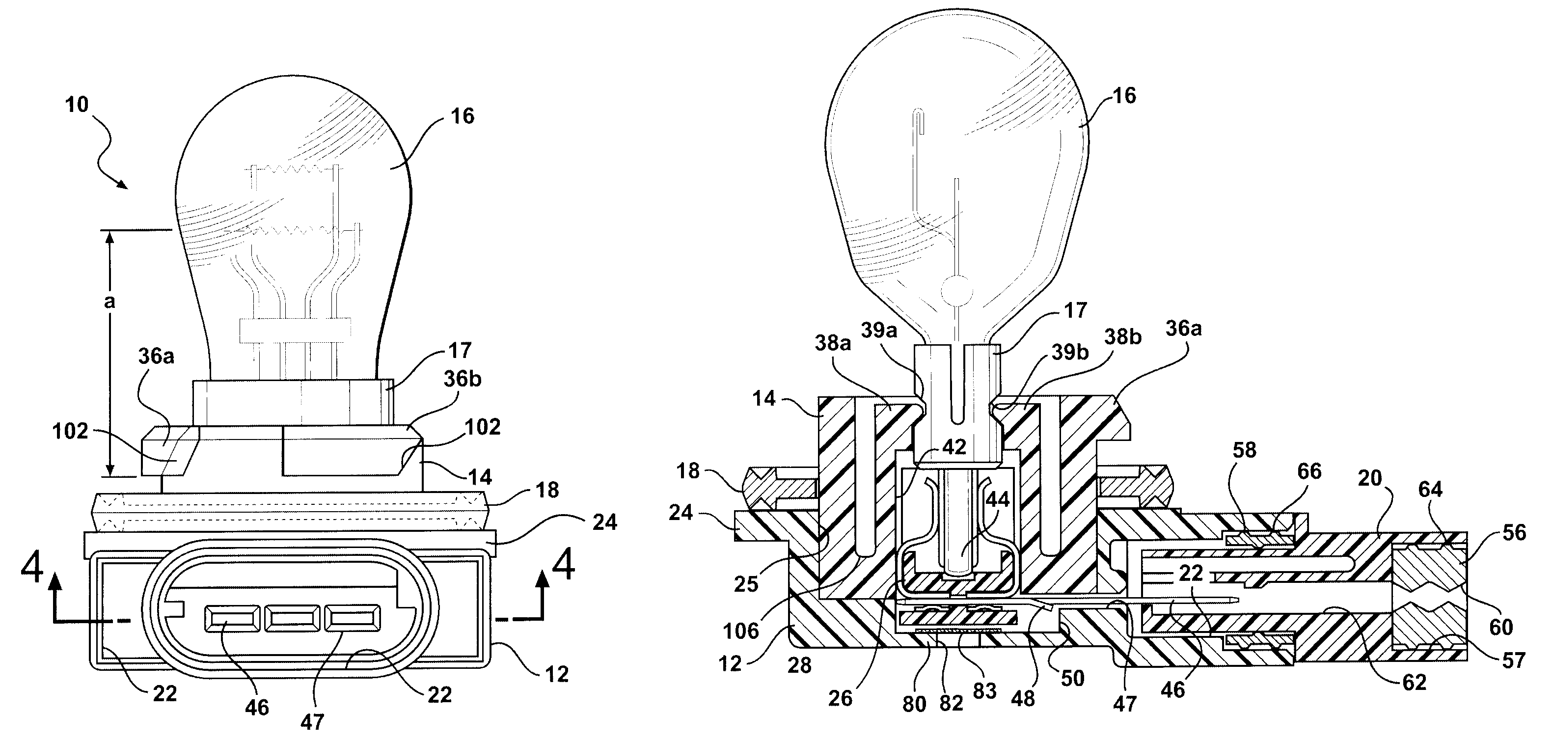
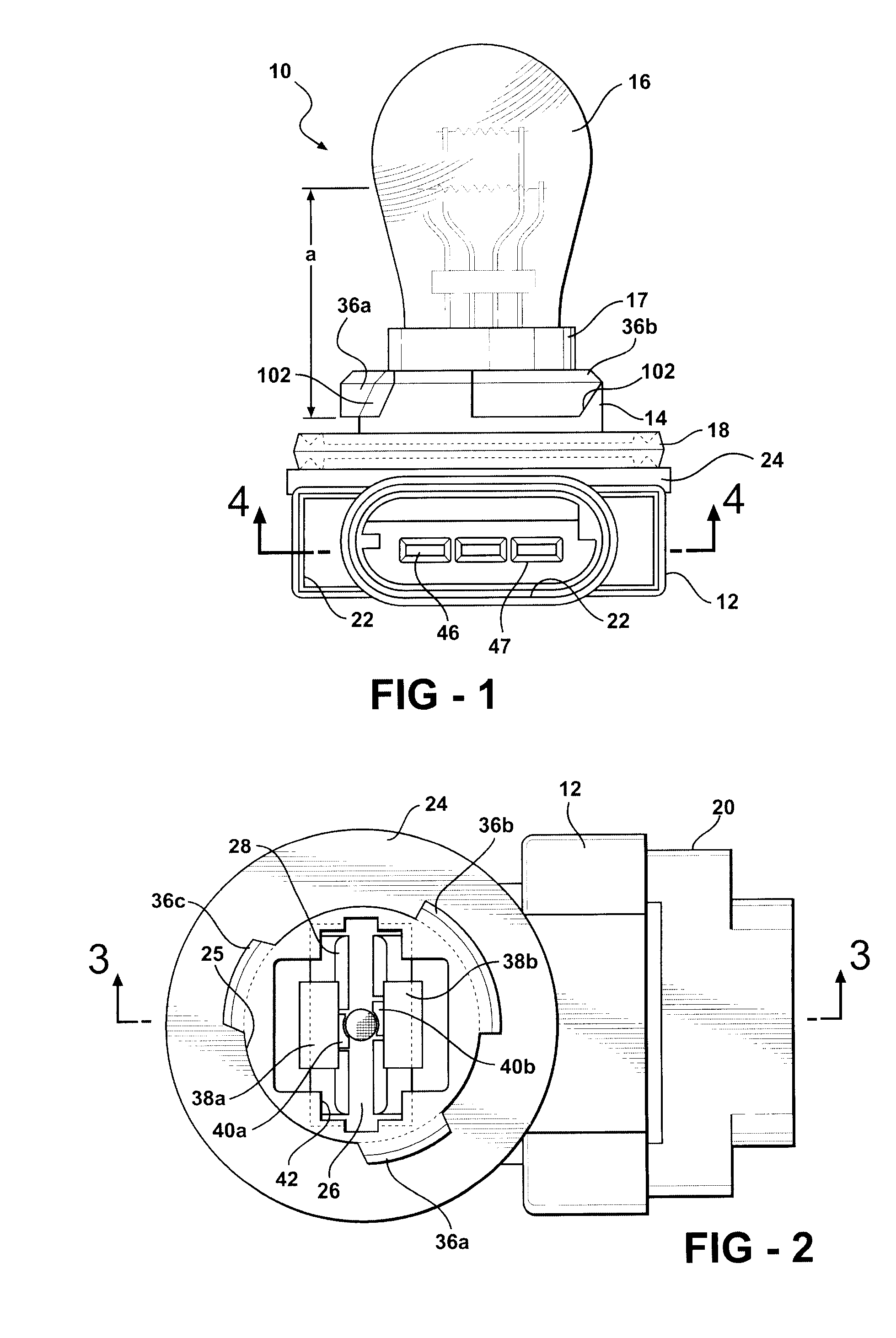
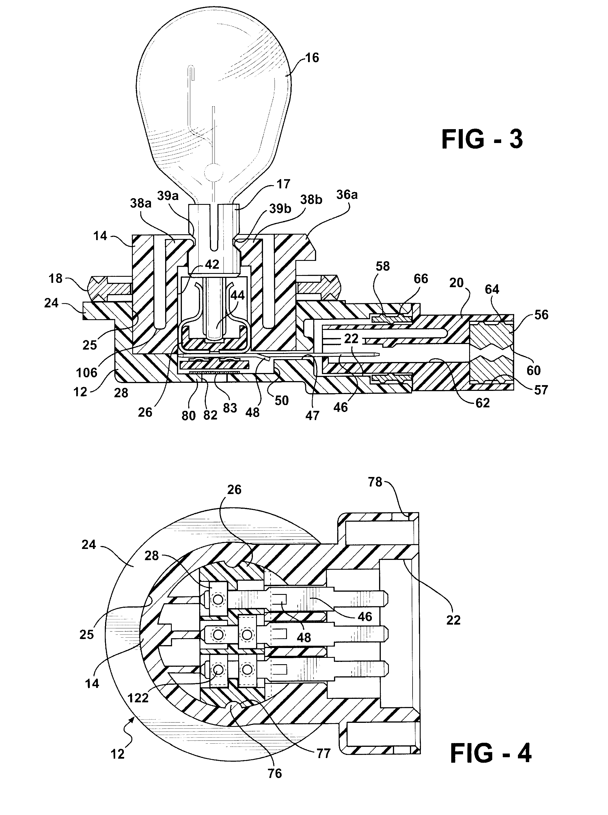
[0045]Referring to the Figures wherein like numerals indicate like or corresponding parts throughout the several views, FIGS. 1-4 show a preferred embodiment of the lamp socket assembly 10. The assembly includes a base or housing 12, a body 14, and a bulb or lamp 16 shown here as a two-filament lamp. It should be noted that the lamp socket assembly of the present invention can accommodate lamps with various numbers of filaments. The lamp includes a lamp base 17 which is inserted into lamp socket assembly 10. A flange seal 18 is provided for sealing the lamp socket assembly 10 to a panel, such as an automobile panel. A socket connector 20, as best shown in FIGS. 2 and 3, is inserted into a socket 22. Socket connector 20 includes electrical connector terminals (not shown) which are connected to wires (not shown) for connecting the lamp socket assembly to a source of electric power.

[0046]It should be noted that, while not illustrated herein, the socket assembly may be used with a seale...


PUM


Abstract

A lamp and socket assembly (10) comprises a housing (12) including a socket cavity (25). The socket cavity (25) is defined by side walls and a bottom wall (80). A vent hole (82) passes though the bottom wall (80) of the socket cavity. A lamp (16) has a lamp base (17). A lamp socket (14) is disposed in the socket cavity (25) and includes a through passage (42) for receiving the lamp base (17) and at least one retaining finger (38a, 38b) for retaining the lamp base (17) in the through passage (42). An electrical contact insert (26) is received in the socket cavity (25). A plurality of electrical contacts (28) are received in and retained by the contact insert (26). A plurality of blade terminals (46) are interlocked with the contact insert (26), with respective ones of the contacts (28), and with the housing (12). A hydrophobic and / or oleophobic vent patch (83) is disposed in the socket cavity (25) and completely covers the vent hole (82) to permit trapped vapors and gasses to escape while repelling water and / or oil.

Description

CROSS REFERENCE TO RELATED APPLICATIONS[0001]This application claims the benefit of priority to U.S. Provisional Patent Application No. 60 / 865,469 filed Nov. 13, 2006.BACKGROUND OF THE INVENTION[0002]1. Field of the Invention[0003]The subject invention relates to lamp socket assemblies and in particular to vented lamp socket assemblies of the type used in tail lights of automobiles and the like.[0004]2. Related Art[0005]All sealed automotive lamp assemblies must address pressure rises due to the heat generated by the lamp, material outgassing, as well as from moisture intrusion. According to prior art techniques, this problem is usually addressed through some type of vent system to equalize pressure within the enclosure and allow moisture to escape. Such vents most often take the form of a hole formed through the lamp housing. The hole is sometimes left open, but there is concern with dirt and excessive water intrusion such that manufacturers often cover the vent hole to prevent dir...

Claims


Application Information

Patent Timeline
Patent Type & Authority Patents(United States)
IPC IPC(8): H01R4/60
CPCF21S48/337F21V19/00H01R13/5227F21V31/03F21V19/0005F21S45/37
Inventor OWEN, SR., ROBERT H.MOLINARO, MARK
Owner TENNECO INC
Why Eureka
Try Eureka