Catheter with removable balloon protector and stent delivery system with removable stent protector

a technology of stents and balloons, which is applied in the field of balloon catheters, can solve the problems of blocked coronary arteries, etc., and achieve the effects of easing the sliding of the sleeve, and reducing the profile of the sten

Inactive Publication Date: 2009-11-17
BOSTON SCI SCIMED INC
View PDF27 Cites 101 Cited by
  • Summary
  • Abstract
  • Description
  • Claims
  • Application Information

AI Technical Summary

Benefits of technology

[0016]The present invention also provides a stent delivery system including a catheter having an expandable distal portion constructed and arranged for expanding the outer diameter of the catheter from a contracted state to an expanded state. The distal portion of the catheter may further comprise one or two dams (also referred to as enlarged portions, stops, bumpers, longitudinal motion preventers, or the like) and a balloon. A stent is positioned around the distal portion of the catheter. Where there is a single dam, the stent may be positioned either proximally or distally of the dam. In an embodiment having a single proximal dam, the stent is positioned distally of the proximal dam. In an embodiment having a single distal dam, the stent is positioned proximally of the distal dam. Where two spaced dams are present, the stent is positioned between the dams, i.e. distally of the proximal dam and proximally of the distal darn. The stent has a contracted condition, being sized in the contracted condition to closely surround the balloon (the balloon in such instance being folded or otherwise collapsed), and being expandable to an expanded condition. The stent delivery system further comprises a stent protector means comprising removable first and second sleeves. The first removable (inner) sleeve is positioned around the stent and between the dams, the inner sleeve being made of a lubricious material and further comprising a first end, a second end and an expansion slit extending therethrough. The slit may extend from end to end. Alternatively, the slit may extend along a predetermined length of the sleeve, the rest of the length of the sleeve comprising a continuous tube. The continuous tube may further comprise a dimpled region and a straight tubular region. The slit provides a variable inner diameter to ease sliding the sleeve over the balloon and stent. The second removable (outer) sleeve is positioned over the stent, first sleeve and dams, the outer sleeve having a constrictive relationship with the inner sleeve. The outer sleeve thereby provides an additional compressive force to reduce the profile of the stent and collapsed balloon. For example, the outer sleeve may have an inner diameter less than the outer diameter of the inner sleeve, whereby when compressed by the outer sleeve, the inner sleeve will have an inner diameter approximately equal to or less than the outer profile of the collapsed balloon over the dam(s). The stent protector means provides reduction of the profile of the compressed stent over the collapsed balloon.

Problems solved by technology

Coronary arteries may also become blocked due to formation of thrombus.

Method used


Image

  • Catheter with removable balloon protector and stent delivery system with removable stent protector
  • Catheter with removable balloon protector and stent delivery system with removable stent protector
  • Catheter with removable balloon protector and stent delivery system with removable stent protector

Examples


Embodiment Construction

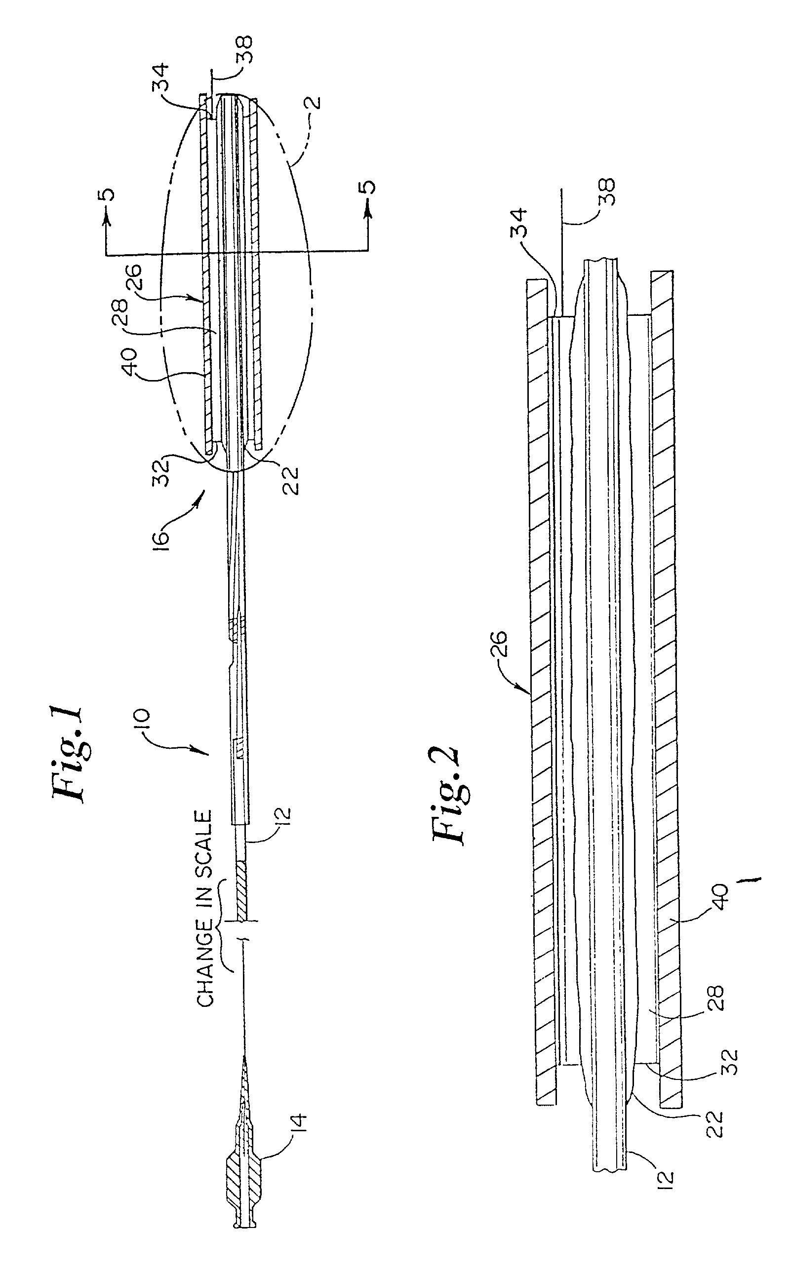
[0065]Referring to FIGS. 1-2, a medical device comprising a balloon catheter with a balloon protector according to the present invention is generally indicated at 10.

[0066]As shown at FIG. 1, catheter 12 has a shaft 13, a proximal portion 14 and a distal portion, indicated generally at 16, in longitudinal section view which is enlarged relative to the view of the proximal portion of said catheter. Distal portion 16 is fixed to catheter 12 by standard means known in the art. For instance, distal portion 16 may be bonded at its ends by adhesive to the catheter in an integral manner, or may be made one-piece with the catheter as is known in the art. Distal end portion 16 comprises balloon 22, which is constructed and arranged for expansion from a contracted state to an expanded state. FIG. 2 shows distal end portion 16 in an even more enlarged longitudinal cross-sectional view.

[0067]Balloon 22 may be of any length. For instance, balloon 22 may be about 15 mm long. This length, however,...


PUM


Abstract

A protective sleeve for a balloon dilatation catheter includes an elongate tubular member having a neck portion and a slit extending along the entire length of the tubular member from a proximal end to a distal end thereof, wherein a distal portion of the tubular member is flared from the neck portion to the distal end of the tubular member to define an enlarged funnel-like opening.

Description

CROSS REFERENCE TO RELATED APPLICATIONS[0001]This application is a Continuation-in-part of U.S. patent application Ser. No. 08 / 812,351 filed Mar. 5, 1997, now U.S. Pat. No. 5,893,868 incorporated herein by reference.BACKGROUND OF THE INVENTION[0002]1. Field of the Invention[0003]The present invention relates generally to catheters having an expandable balloon and to premounted balloon expandable stent balloon catheters, and specifically to a dilatation balloon catheter with a balloon protector means or a stent delivery system with a balloon and stent protector means.[0004]2. Description of Related Art[0005]Percutaneous transluminal coronary angioplasty (PTCA) is a procedure which is well established for the treatment of blockages in the coronary arteries. Blockages may occur from cholesterol precipitation on the coronary wall which may be in any stage from initial deposit through aged lesions. Coronary arteries may also become blocked due to formation of thrombus.[0006]The most wide...

Claims


Application Information

Patent Timeline
Patent Type & Authority Patents(United States)
IPC IPC(8): A61M5/178A61F2/958A61M25/00A61M25/10A61M29/02
CPCA61F2/0095A61F2/958A61M25/104A61M2025/1081A61F2002/9583
Inventor HOLMAN, THOMAS J.ELLIS, LOUIS G.OLSON, GREGORY K.LORENTZEN CORNELIUS, LINDA R.TRAXLER, RICHARD J.HANSON, SCOTT M.
Owner BOSTON SCI SCIMED INC
Why Eureka
Try Eureka