Vibrator

a technology of vibrating motors and rotors, applied in the field of vibrating motors, to achieve the effect of increasing the amplitud

Inactive Publication Date: 2009-11-17
CITIZEN ELECTRONICS CO LTD
View PDF10 Cites 59 Cited by
  • Summary
  • Abstract
  • Description
  • Claims
  • Application Information

AI Technical Summary

Benefits of technology

[0012]Thus, the vibrator according to the present invention is not provided with a ring such as that used in the above-described related-art vibrator to mount the first suspension and therefore allows the magnetic circuit assembly to vibrate with an increased amplitude. In addition, the spring portion of the first suspension is not provided in a limited annular space between the outer and inner peripheral portions as in the related-art vibrator. Therefore, the spring portion can be lengthened and made resistant to metal fatigue as compared to the related-art vibrator.

Problems solved by technology

In addition, the spring portion of the first suspension is not provided in a limited annular space between the outer and inner peripheral portions as in the related-art vibrator.

Method used


Image

  • Vibrator
  • Vibrator
  • Vibrator

Examples


Embodiment Construction

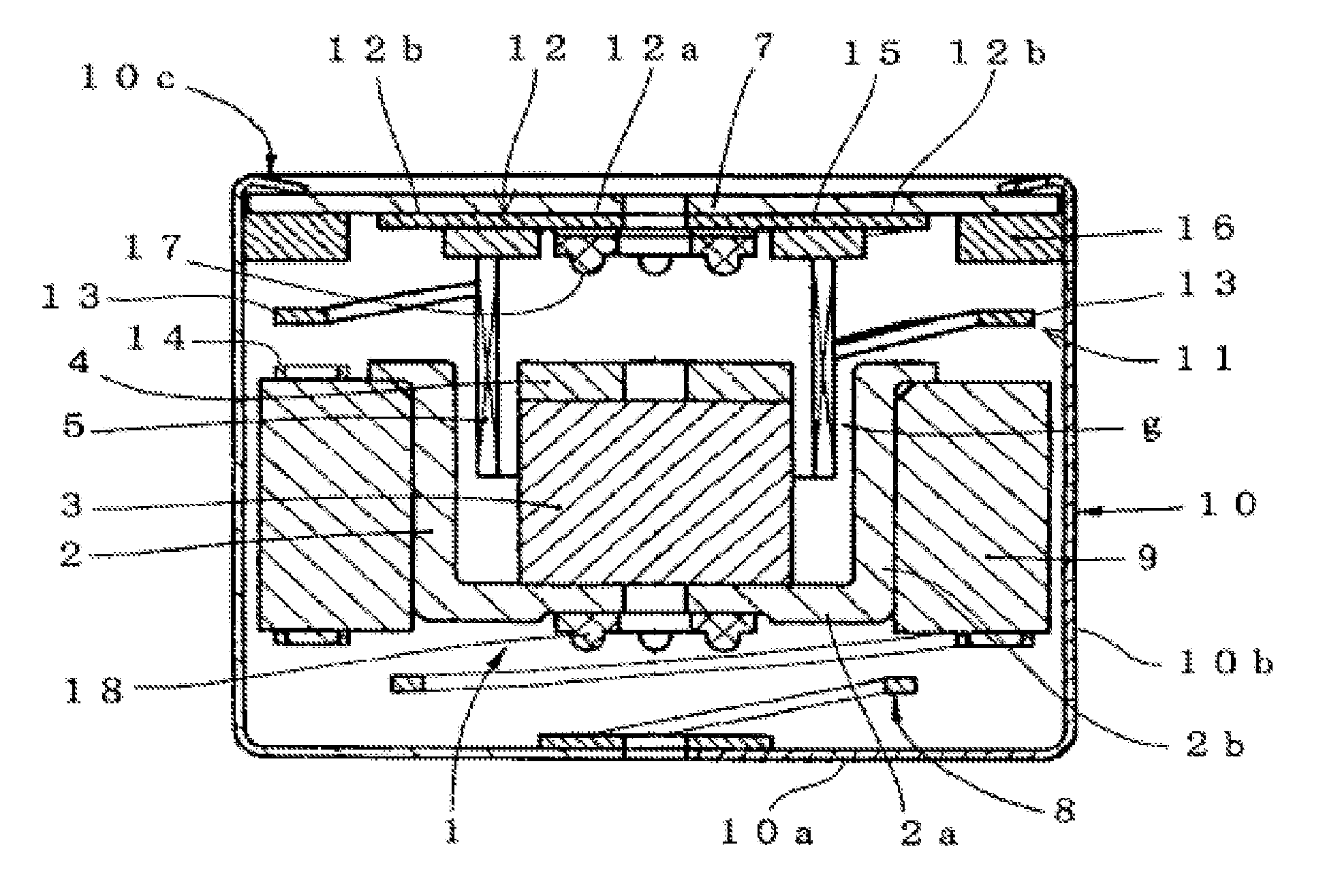
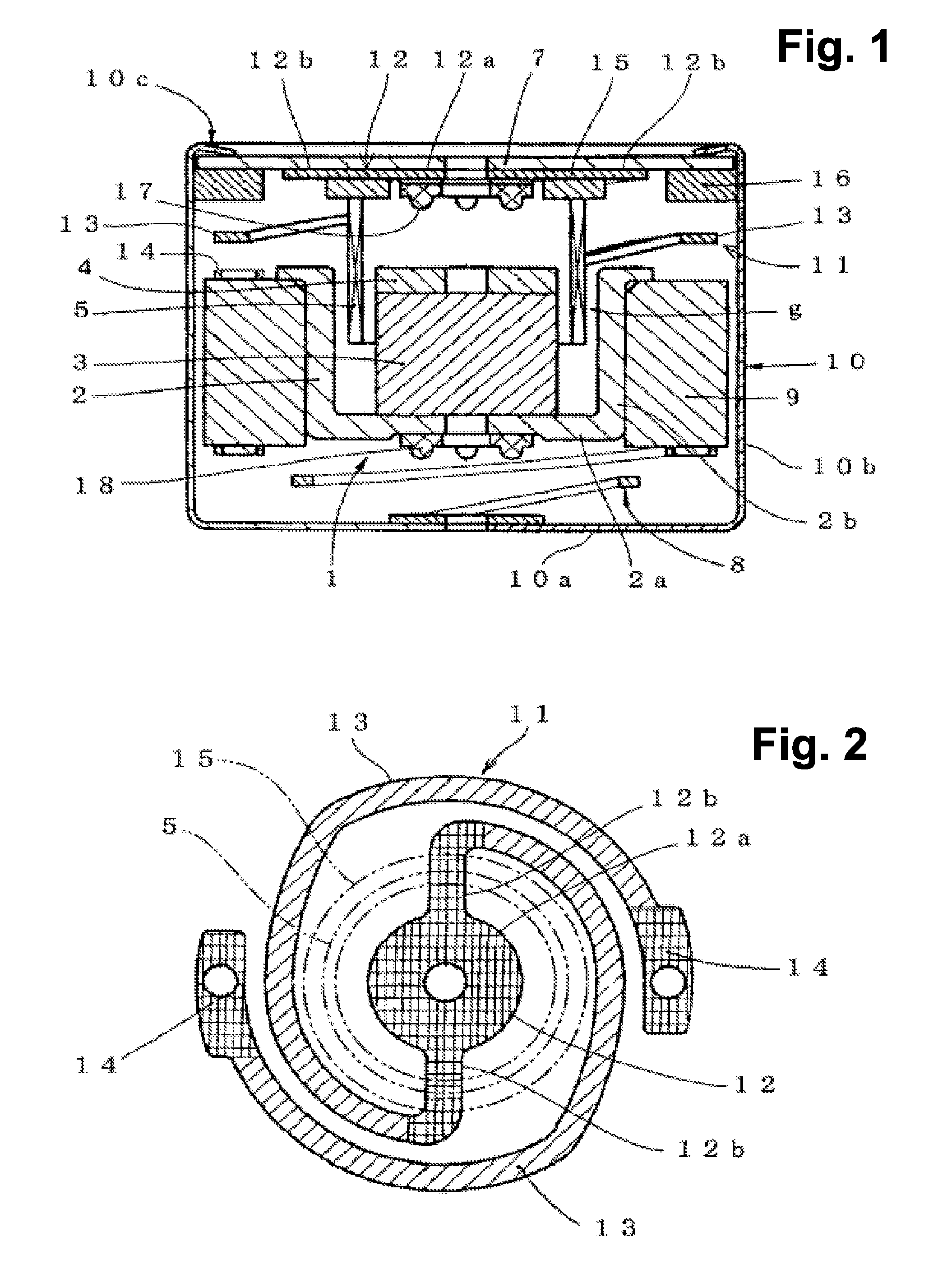
[0023]An embodiment of the present invention will be described below in detail with reference to FIGS. 1 and 2.

[0024]A vibrator according to the embodiment of the present invention has a cup-shaped casing 10, a substrate 7 provided to close an upper end opening of the casing 10, a magnetic circuit assembly 1 provided in the casing 10, a first suspension 11 and a second suspension 8 that support the magnetic circuit assembly 1 from above and below, and a voice coil 5 secured to the substrate 7 and inserted into a magnetic gap g in the magnetic circuit assembly 1.

[0025]The casing 10 has a bottom wall 10a and a tubular side wall 10b extending from the bottom wall 10a. The substrate 7 has wiring (not shown) for connecting the voice coil 5 to a circuit provided outside the vibrator.

[0026]The magnetic circuit assembly 1 includes a cup-shaped yoke 2 having a bottom wall portion 2a disposed to face the bottom wall 10a of the casing 10 and a tubular peripheral wall portion 2b extending from ...


PUM

PropertyMeasurementUnit
angleaaaaaaaaaa
angleaaaaaaaaaa
magneticaaaaaaaaaa

Abstract

A vibrator has a cup-shaped casing, a substrate provided to close an upper end opening of the casing, a magnetic circuit assembly provided in the casing, a first suspension and a second suspension that support the magnetic circuit assembly from above and below, and a voice coil secured to the substrate and inserted into a magnetic gap in the magnetic circuit assembly. The first suspension has an inner fixed portion that is secured to the substrate and that has a radially inner ring-shaped portion and a pair of extensions extending radially outward from mutually diametrically opposing positions on the ring-shaped portion. The first suspension further has a pair of leaf spring portions arcuately extending from the respective extensions through an angle of about 270 ° in symmetry to each other around the axis of the voice coil. Further, the first suspension has outer fixed portions disposed at the distal end portions of the leaf spring portions and secured to the upper end surface of a weight of the magnetic circuit assembly.

Description

[0001]This application claims priority under 35 U.S.C. §119 to Japanese Patent Application No. JP2006-105698 filed Apr. 6 2006, the entire content of which is hereby incorporated by reference.BACKGROUND OF THE INVENTION[0002]1. Field of the Invention[0003]The present invention relates to vibrators that may be incorporated into mobile communications devices such as cellular phones and personal digital assistants (PDAs) to inform the user of an incoming call.[0004]2. Description of the Related Art[0005]Conventionally, mobile communications devices such as cellular phones and PDAs are arranged to inform the user of an incoming call by selectively generating beep sound or melody, or vibrating the housing of the device instead of producing sound. For this purpose, the conventional practice is to employ a structure incorporating a combination of a sound-generating speaker categorized as a microspeaker and a vibrator that generates vibration by rotating an eccentric weight with a small mot...

Claims


Application Information

Patent Timeline
Patent Type & Authority Patents(United States)
IPC IPC(8): H01F7/08H02K33/00H04R9/02
CPCB06B1/045H04R11/00H02K33/16F16F1/18H04M1/03H04R11/06B06B1/04
Inventor MIURA, NAOKI
Owner CITIZEN ELECTRONICS CO LTD
Why Eureka
Try Eureka