Color invariant image fusion of visible and thermal infrared video

a technology of invariant image and video, applied in image enhancement, texturing/coloring, image analysis, etc., can solve the problems of confusion between visible and thermal infrared contrast, inability to adapt to many applications, lack of invariance to visible illumination changes, etc., and achieve intuitive and informative image fusion algorithms for single still frames. not necessarily appropriate, the effect of enhancing the visualization schem

Inactive Publication Date: 2009-11-17
EQUINOX CORP
View PDF4 Cites 240 Cited by
  • Summary
  • Abstract
  • Description
  • Claims
  • Application Information

AI Technical Summary

Benefits of technology

[0007]For a more specific category of image fusion this invention teaches a methodology for naturally visualizing the fusion of an image produced from a sub-spectrum of the thermal infrared domain with an image produced from a sub-spectrum of the reflective domain (e.g., visible imaging). At each pixel this is achieved by a set of mappings with two inputs from these respective domains and outputting into a hue, saturation, intensity (HSV) color space such as defined in [Foley, Van Dam Feiner and Hughes, “Computer Graphics: Principles and Practice”, 1990, Addison Wesley]. A key advantage to this image fusion visualization methodology is the color invariance to changes in the reflective domain input value. In this way the color visualization of the thermal infrared domain is preserved for reflective illumination variations that occur in a scene. To human perception this segregates the contrast detail for the thermal infrared image as distinct from the contrast detail of the reflective domain image not just for still frames but for continuous video operation viewing a dynamic scene.

Problems solved by technology

The key issues for practical portable field applications are how to effectively visualize these two complementary modalities at video rates with sufficiently low power consumption and small form factor.
However, such a visualization scheme is usually not suitable for many applications with major drawbacks being the lack of invariance to visible illumination changes and confusion between visible and thermal infrared contrast.
Furthermore, experience has shown that image fusion algorithms appearing intuitive and informative for single still frames are not necessarily appropriate under conditions of continuous operation, particularly if a human observer is immersed in such an environment for significant lengths of time.

Method used


Image

  • Color invariant image fusion of visible and thermal infrared video
  • Color invariant image fusion of visible and thermal infrared video
  • Color invariant image fusion of visible and thermal infrared video

Examples


Embodiment Construction

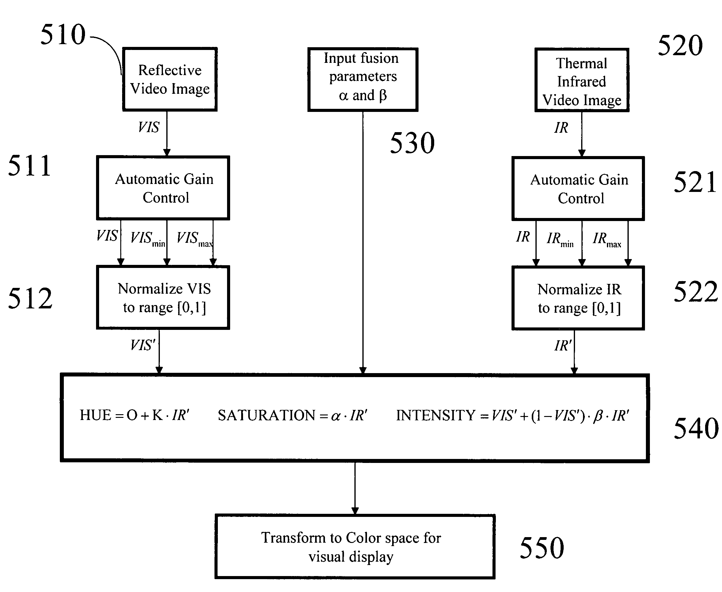
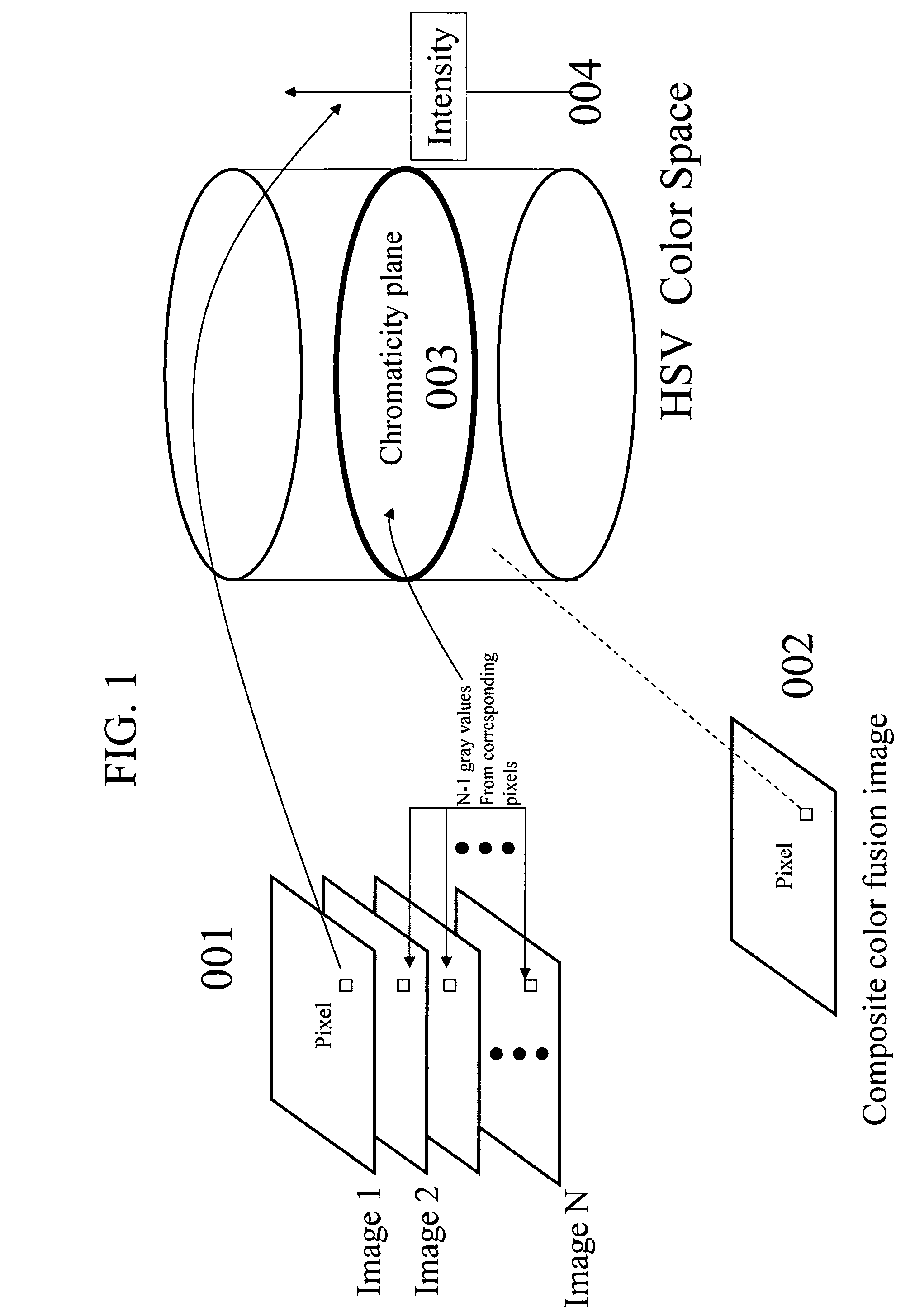
[0025]FIG. 1 shows the methodology of forming a color composite image 002 from N gray level images 001 by decomposing the color space representation into its chromaticity planes 003 and intensity 004 (in this case HSV space further described in FIG. 5) and making the mapping into chromaticity plane coordinates only dependent on the corresponding gray values of the latter N−1 images and independent of the gray values of the first image. It is important to note that the HSV color space 405 illustrated in FIG. 5 is only one such color space that can be naturally decomposed into segregated 2-D color planes 404 orthogonal to the 1-D intensity axis 403. For instance, the well-known CIE color space 410 and other variants that are psychophysically accurate, and RGB tri-stimulus color spaces 420 can be used just as well [Wyszecki, Stiles, “Color Science: Concepts and methods, Quantitative Data and Formulae”, 1982, John Wiley & Sons]. This certainly does not exhaust the list of possible color...


PUM


Abstract

A methodology for forming a composite color image fusion from a set of N gray level images takes advantage of the natural decomposition of color spaces into 2-D chromaticity planes and 1-D intensity. This is applied to the color fusion of thermal infrared and reflective domain (e.g., visible) images whereby chromaticity representation of this fusion is invariant to changes in reflective illumination.

Description

CROSS REFERENCE TO RELATED APPLICATIONS[0001]This application claims the benefit, under 35 U.S.C. 119(e), of U.S. Provisional Application No. 60 / 560,968, filed Apr. 12, 2004 the disclosure of which is hereby incorporated herein by reference.BACKGROUND OF THE INVENTION[0002]1. Field of the Invention[0003]The invention described herein relates to the methodology of forming a fused composite color image from source gray level images, with application to visualizing the fusion of video imaging in the infrared spectrum (e.g., thermal infrared) with video imaging in the reflective spectrum (e.g., visible).[0004]2. Description of the Background Art[0005]The advantages of image fusion of the visible and thermal infrared modalities have been studied for quite some time [S. Horn et al., “Fused Reflected / Emitted Light Sensors”, Proceedings of SPIE Infrared Technology and Applications XXVII, Vol. 4369, pp. 1-13, 2001]. Visible imaging (which can also include intensified Near-IR imaging) reveals...

Claims


Application Information

Patent Timeline
Patent Type & Authority Patents(United States)
IPC IPC(8): G06K9/40G06K9/36
CPCG06T5/50G06T11/001G06T2207/20221G06T2207/10048G06T2207/10016
Inventor WOLFF, LAWRENCE B.SOCOLINSKY, DIEGO A.EVELAND, CHRISTOPHER K.
Owner EQUINOX CORP
Why Eureka
Try Eureka