Wrapping cart machine and method of wrapping

a cart machine and wrapping technology, applied in the field of wrapping machines, can solve the problems of slow and at times difficult use of prior art wrapping carts, difficult positioning and adjustment of wrapping material tension, and inability to effectively adjust tension, so as to facilitate the positioning of wrapping material and facilitate the effect of positioning

Inactive Publication Date: 2009-11-24
VANDERHEIDEN PATRICK J +1
View PDF19 Cites 22 Cited by
  • Summary
  • Abstract
  • Description
  • Claims
  • Application Information

AI Technical Summary

Benefits of technology

[0007]It is a still further object of the invention to provide a fast and economical method of wrapping apparatuses and materials.
[0008]It is a still further object of the invention to provide a novel wrapping cart capable of wrapping materials with exceptional speed.
[0013]It is a still further object of the invention to provide a multiple roll wrapping apparatus in which individual rolls may be independently removed and have the tension on the wrapping material adjusted.
[0014]It is a still further object of the invention to provide wrapping apparatus and a method in which the user may bring the wrapping material to the desired elevation easily and conveniently.
[0015]In accordance with the above and further objects of the invention, an electrically controlled drive mechanism on a vehicle such as a push / pull cart positions rolls of wrapping material (wrapping paper or wrapping film) in elevation under the control of a switch on the handle of the vehicle. In the preferred embodiment, the drive mechanism is an electric actuator which can be actuated by the user from his location when using the vehicle. In the preferred embodiment, the vehicle is a push / pull cart with four wheels, two forward wheels being at the front of the push / pull cart and two rear wheels being at the rear of the cart with the two rear wheels being steerable by a handle mounted at the rear of the cart. However, the push / pull cart may also include three wheels, two forward wheels being at the front of the push / pull cart and one rear wheel being at the rear of the cart with the rear wheel being steerable by a handle mounted at the rear of the cart. Multiple rolls of wrapping material are mounted at vertically spaced positions and simultaneously wrapped around objects or apparatuses to be wrapped. This reduces the time in which the wrapping is performed. For example, with two rolls, two wraps may be applied simultaneously to reduce the time of wrapping by as much as twofold. Similarly, three rolls vertically spaced may reduce the time as much as by threefold and reduce the number of times that a particular item must be encircled by the operator.
[0017]The wrapping vehicle or machine of this invention has several advantages, such as for example: (1) it is labor saving; (2) it is fast because of the ability to wrap more than one turn of wrapping material in one revolution about the objects being wrapped; (3) it permits easy positioning of the wrapping material in elevation; and (4) it permits effective adjustment of tension on the rolls of wrapping material.

Problems solved by technology

These prior art wrapping carts have a disadvantage of being slow and at times difficult to use.
Moreover, the positioning and adjustment as to tension of the rolls of wrapping material are clumsy and difficult.

Method used


Image

  • Wrapping cart machine and method of wrapping
  • Wrapping cart machine and method of wrapping
  • Wrapping cart machine and method of wrapping

Examples


Embodiment Construction

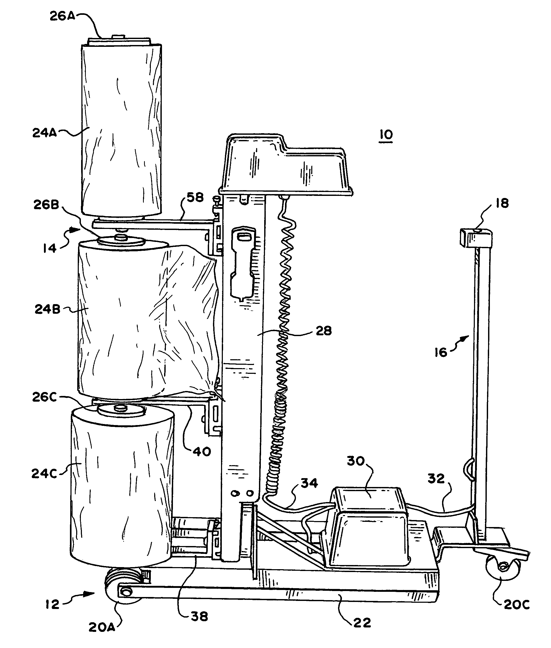
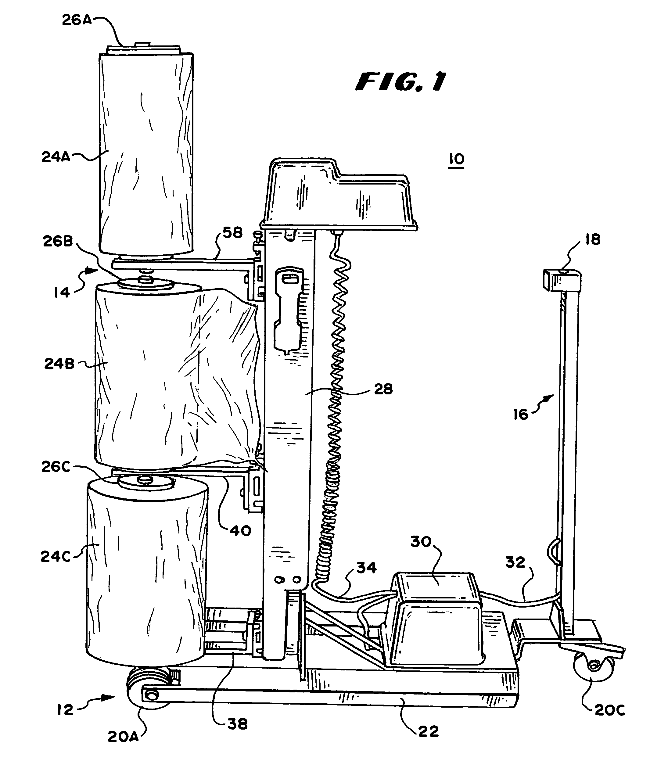
[0029]In FIG. 1, there is shown a perspective view of a wrapping vehicle 10 having a vehicle bed 12, a wrapping material assembly 14 and a handle assembly 16. In the embodiment of FIG. 1, the vehicle 10 is a push / pull cart and the handle assembly 16 includes an actuator switch assembly 18 that controls the vertical location of wrapping material mounted to the vehicle. The vehicle bed 12 in FIG. 1 includes three wheels 20A-20C (wheels 20A and 20C being shown in FIG. 1) and a horizontal support 22. Two wheels, 20A and 20B are mounted forward on the bed 12 (only 20A being shown in FIG. 1) and a third wheel 20C is mounted in the back. The third wheel 20C is pivotable to steer the vehicle. While a three-wheeled push / pull cart is shown in FIG. 1, a four-wheeled push / pull cart could be used having two forward wheels at the front of the push / pull cart and two rear wheels (FIG. 8) at the rear of the cart with the two rear wheels being pivotable by the handle mounted at the rear of the cart. ...


PUM

PropertyMeasurementUnit
widthsaaaaaaaaaa
widthaaaaaaaaaa
tensionaaaaaaaaaa

Abstract

To palletize packages, a wrapping vehicle includes a vertically mounted drive screw having a plurality of ball nuts mounted at wrapping-effective distances from each other on the vertically mounted drive screw. Each ball-nut has a corresponding cantilever mounted to the ball nut to support a roll of wrapping material. A tension adjustment mechanism is mounted to adjust the resistance to motion of each roll of wrapping material and thus the tension on the wrapping material. The ball nuts are each connected to side support guide plates positioned to slide against the sides of mast housing the drive screw wherein said ball nuts are supported against tilting movement.

Description

RELATED CASES[0001]This application is a continuation in part application of U.S. provisional patent application 60 / 878,303, filed Jan. 2, 2007, by Patrick J. Vanderheiden and Michael A. Herman. The benefit of provisional patent application 60 / 878,303 is claimed.BACKGROUND OF THE INVENTION[0002]This invention relates to wrapping machines and methods of using them.[0003]It is known to mount rolls of wrapping material such as for example stretch wrapping plastic on movable carts such as push carts and to use the movable carts to wrap materials and apparatuses in place. A typical movable wrapping cart is easily maneuverable by hand to permit circling of the object or objects to be wrapped. One end of a roll of wrapping material is fastened to the objects at a starting point and the roll is moved around the objects to wrap them together. Commonly, the objects are positioned together on a pallet and stretch wrap material is wound around them to hold them together in a process referred to...

Claims


Application Information

Patent Timeline
Patent Type & Authority Patents(United States)
IPC IPC(8): B65B53/00
CPCB65B11/025
Inventor VANDERHEIDEN, PATRICK J.HERMAN, MICHAEL A.
Owner VANDERHEIDEN PATRICK J
Why Eureka
Try Eureka