
Force feedback poppet valve having an integrated pressure compensator

a pressure compensator and force feedback technology, applied in the direction of fluid pressure control, servomotors, instruments, etc., can solve the problems of unfavorable pressure fluctuations, inconsistent and/or unexpected actuator movements, and undesirable pressure fluctuations of fluid supplied to one actuator

Active Publication Date: 2009-11-24
CATERPILLAR INC +1
View PDF84 Cites 26 Cited by
  • Summary
  • Abstract
  • Description
  • Claims
  • Application Information

AI Technical Summary

Benefits of technology

The present disclosure is directed to a force feedback poppet valve with an integrated pressure compensator. The valve includes a main chamber with a first port and a second port. It also includes a main poppet that forms a control chamber and can be moved between an open position and a closed position to control fluid flow between the two ports. The valve also has a pilot valve with a pilot poppet to control fluid flow between the control chamber and the first port through a second passage. The valve also includes a pressure compensator that is connected to the second port through a first passage and to the first port through a third passage. The valve also includes springs that provide a force proportional to the distance between the main poppet and the pilot poppet, as well as the distance between the pressure compensator and the pilot poppet. The technical effect of this design is that it allows for precise control of fluid flow through the valve with a high degree of accuracy and responsiveness.

Problems solved by technology

Machine hydraulic circuits that fluidly connect multiple actuators to a common pump may experience undesirable pressure fluctuations within the circuits during operation of the actuators.
In particular, the pressure of a fluid supplied to one actuator may undesirably fluctuate in response to operation of a different actuator fluidly connected to the same hydraulic circuit.
These pressure fluctuations may cause inconsistent and / or unexpected actuator movements.
In addition, the pressure fluctuations may be severe enough and / or occur often enough to cause malfunction or premature failure of hydraulic circuit components.
Although the multiple pressure compensating valves of the hydraulic circuit described in the '647 patent may reduce the effect of pressure fluctuations within the hydraulic circuit, because of their number they may increase the cost and complexity of the hydraulic circuit.
In addition, the pressure compensating valves of the '647 patent may not control the pressures within the hydraulic circuit precisely enough for optimal performance of the associated actuator.

Method used


Image

  • Force feedback poppet valve having an integrated pressure compensator
  • Force feedback poppet valve having an integrated pressure compensator
  • Force feedback poppet valve having an integrated pressure compensator

Examples


Embodiment Construction

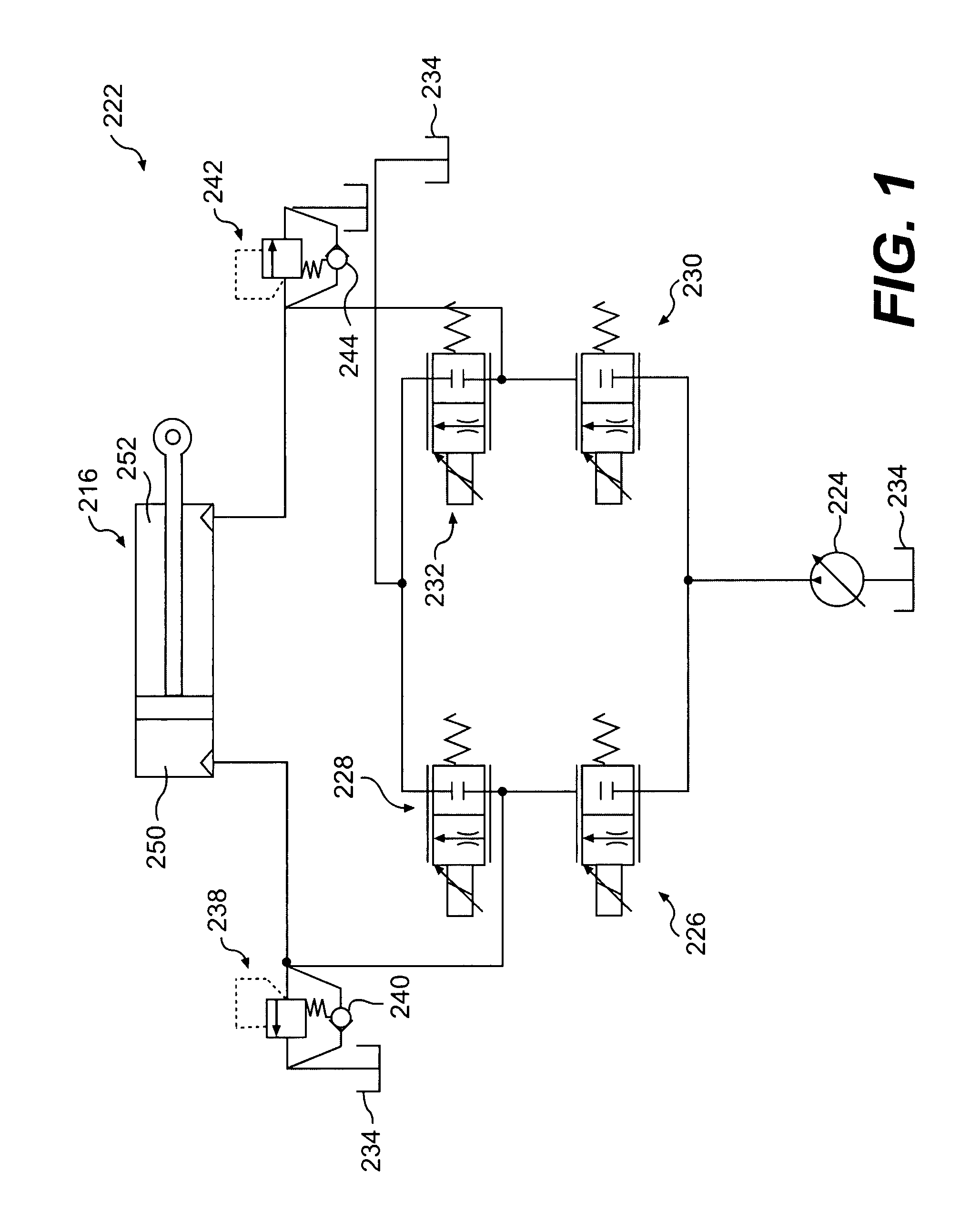
[0013]FIG. 1 illustrates a hydraulic system 222 having a hydraulic actuator 216 movable to control a work implement (not shown). Hydraulic actuator 216 may include a head-end chamber 250 and a rod-end chamber 252. Hydraulic system 222 may further include a source 224 of pressurized fluid directed to move the actuator by way of a head-end supply valve 226, a head-end drain valve 228, a rod-end supply valve 230, and a rod-end drain valve 232. Hydraulic system 222 may also include a tank 234, a head-end pressure relief valve 238, a head-end makeup valve 240, a rod-end pressure relief valve 242, and a rod-end makeup valve 244 that cooperate to maintain desired pressures within hydraulic system 222. It is contemplated that hydraulic system 222 may include additional and / or different components such as, for example, a pressure sensor, a temperature sensor, a position sensor, a controller, an accumulator, and other components known in the art.

[0014]Source 224 may produce a flow of pressuri...


PUM


Abstract

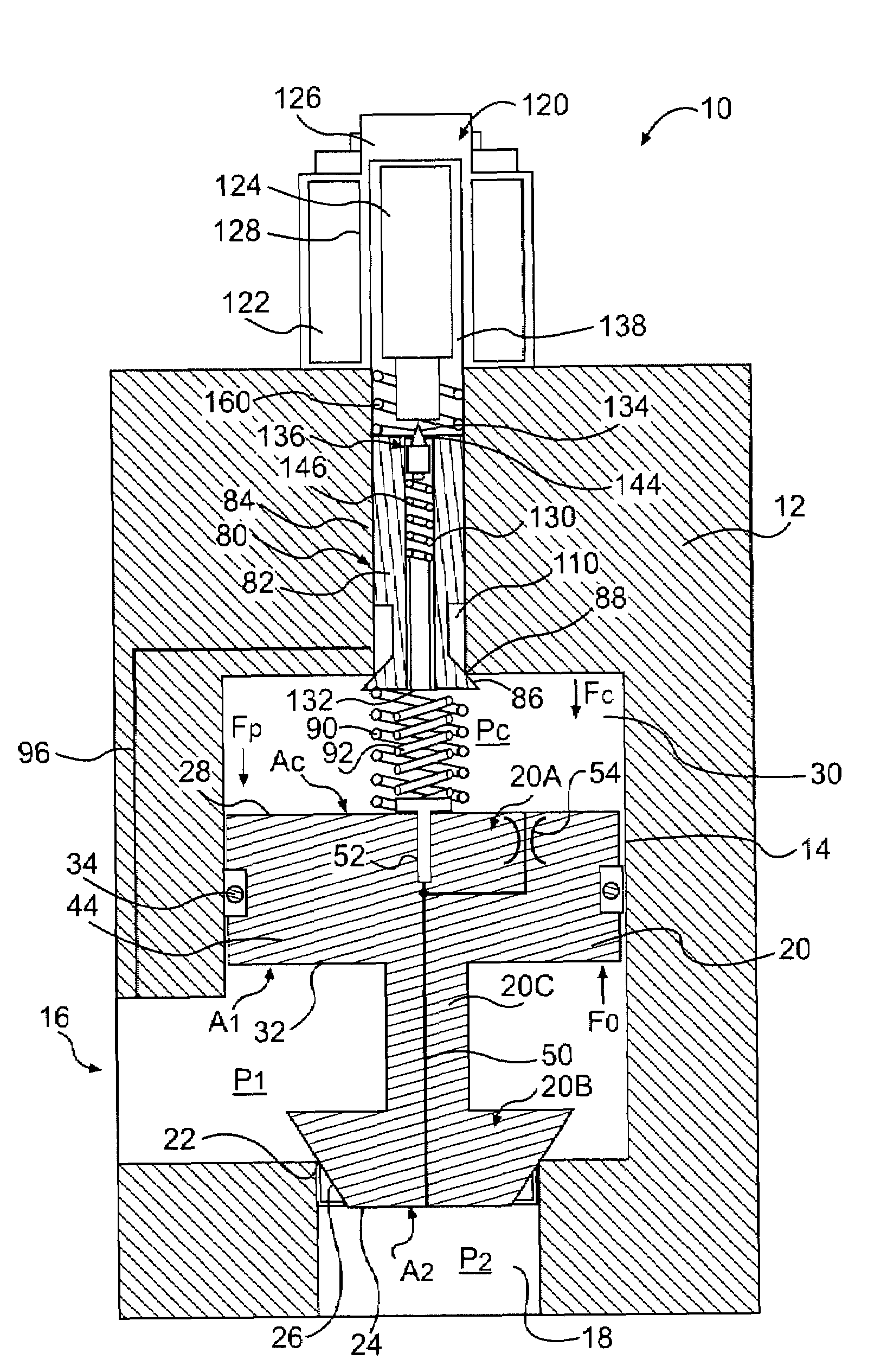
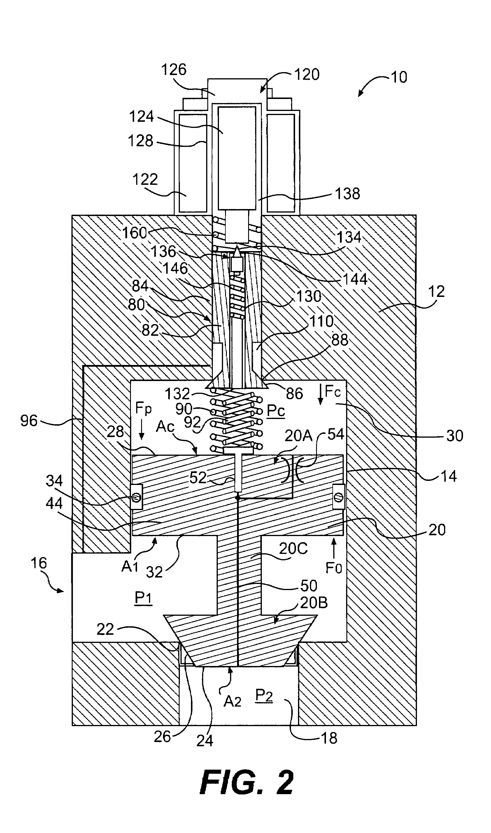
The force feedback poppet valve includes a valve body having a main chamber, a first port, and a second port. The force feedback poppet valve further includes a main poppet disposed within the main chamber and movable between an open position and a closed position to control fluid flow between the first port and the second port. The main poppet forms a control chamber within the main chamber. The force feedback poppet valve further includes a first passage communicating the control chamber with the second port, a second passage communicating the control chamber with the first port, and a pilot valve having a pilot poppet for controlling fluid flow between the control chamber and the first port through the second passage. The force feedback poppet valve further includes a pressure compensator disposed within the main poppet, and fluidly connected to the second port via the first passage. The force feedback poppet valve further includes a first spring coupled between the main poppet and the pilot poppet to provide a force proportional to a distance between the main poppet and the pilot poppet, and a second spring coupled between the pressure compensator and the pilot poppet to provide a force proportional to a distance between the pressure compensator and the pilot poppet.

Description

TECHNICAL FIELD[0001]The present disclosure relates generally to a force feedback poppet valve, and more particularly, to a force feedback poppet valve having an integrated pressure compensator.BACKGROUND[0002]Machines such as, for example, dozers, loaders, excavators, motor graders, and other types of heavy machinery use one or more hydraulic actuators to accomplish a variety of tasks. These actuators are fluidly connected to a pump on the machine that provides pressurized fluid to chambers within the actuators. An electro-hydraulic valve arrangement is typically fluidly connected between the pump and the actuators to control a flow rate and direction of pressurized fluid to and from the chambers of the actuators.[0003]Machine hydraulic circuits that fluidly connect multiple actuators to a common pump may experience undesirable pressure fluctuations within the circuits during operation of the actuators. In particular, the pressure of a fluid supplied to one actuator may undesirably...

Claims


Application Information

Patent Timeline
Patent Type & Authority Patents(United States)
IPC IPC(8): F16K31/40F15B11/00
CPCE02F9/2207E02F9/2267F15B11/006F15B11/05F15B13/0405F15B13/0417F16K31/406F15B13/0433F15B2211/20546F15B2211/30575F15B2211/3144F15B2211/327F15B2211/40553Y10T137/7788G05D16/2097G05D16/024
Inventor MA, PENGFELVANDE KERCKHOVE, PHILIPPE GEORGES
Owner CATERPILLAR INC
Learn More