Multi-band planar inverted-F antenna

a antenna technology, applied in the direction of antenna supports/mountings, resonant antennas, radiating element structural forms, etc., can solve the problems of insufficient bandwidth of art planar inverted-f antennas and inability to work at multiple frequencies, and achieve the effect of enhancing the bandwidth of multi-band planar inverted-f antennas

Inactive Publication Date: 2009-12-01
FIH (HONG KONG) LTD
View PDF2 Cites 34 Cited by
  • Summary
  • Abstract
  • Description
  • Claims
  • Application Information

AI Technical Summary

Benefits of technology

[0010]Accordingly, the present invention provides a multi-band plane inverted-F antenna (PIFA), which includes a radiating unit, a ground unit and a feeding unit. The radiating unit includes a common radiating element, a high-frequency (HF) radiating element and a low-frequency (LF) radiating element. A quasi U-shaped slot is defined between the HF radiating element and the low-frequency LF radiating element. The ground unit is electrically connected to one side of the common radiating element. The feeding unit includes a strip electrically connected to one side of the HF radiating element. The ground unit includes a ground point and an inverted-L short-line connected to the ground point at one end thereof. The inverted-L short-line is also electrically connected to the common radiating element at another end thereof. A loop surface current induced by the inverted-L short-line can advantageously enhance bandwidth of the multi-band planar inverted-F antenna at frequencies of interest.

Problems solved by technology

However, the prior art planar inverted-F antenna has the drawbacks of insufficient bandwidth and inability to work at multiple frequencies (more than dual-band frequencies).
Therefore, it is important issue to provide a multi-band planar inverted-F antenna for mobile phones such as smart phones.

Method used


Image

  • Multi-band planar inverted-F antenna
  • Multi-band planar inverted-F antenna
  • Multi-band planar inverted-F antenna

Examples


Embodiment Construction

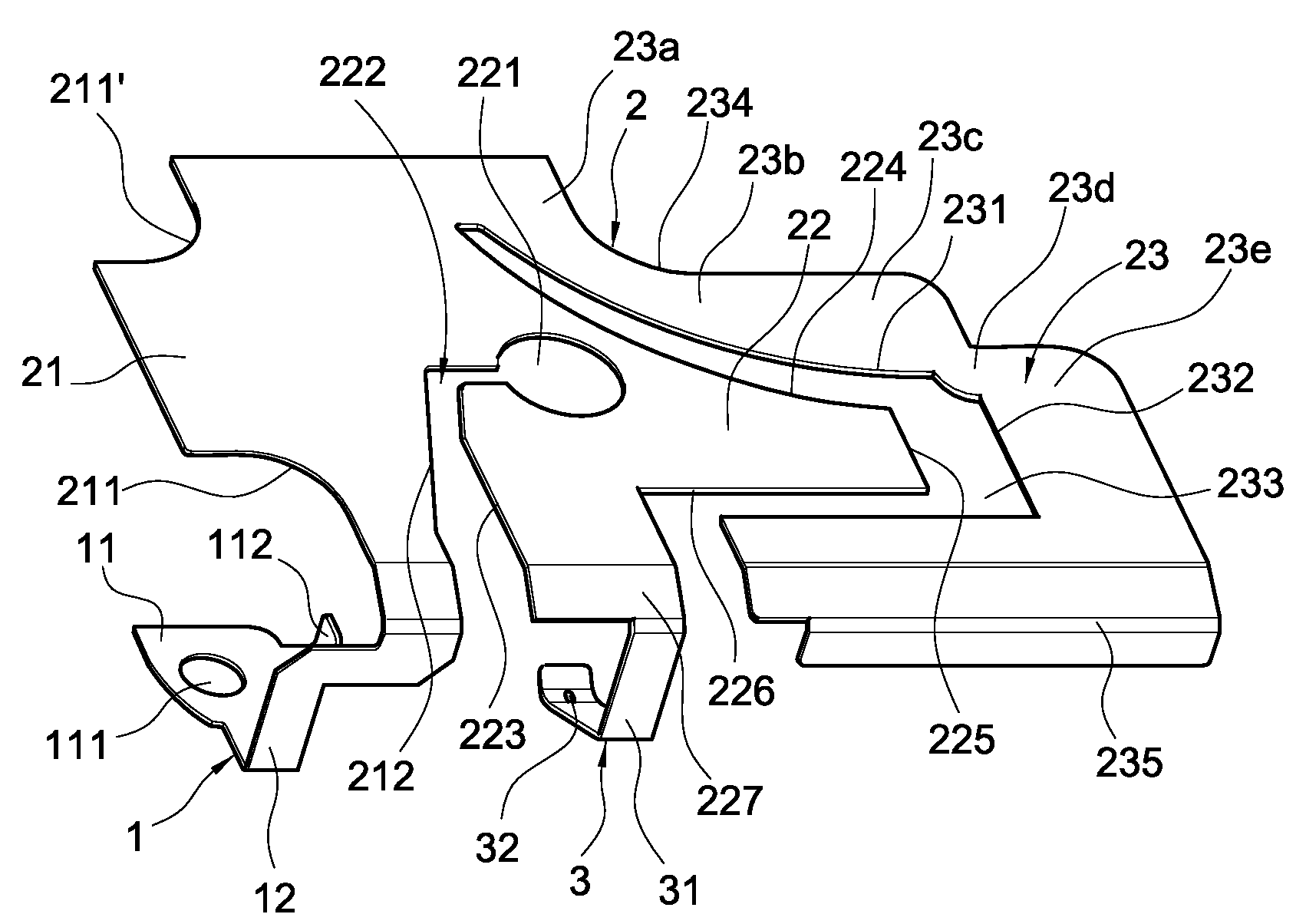
[0023]With reference to FIG. 2, the multi-band planar inverted-F antenna according to a preferred embodiment of the present invention comprises a ground unit 1, a radiating unit 2 and a feeding unit 3.

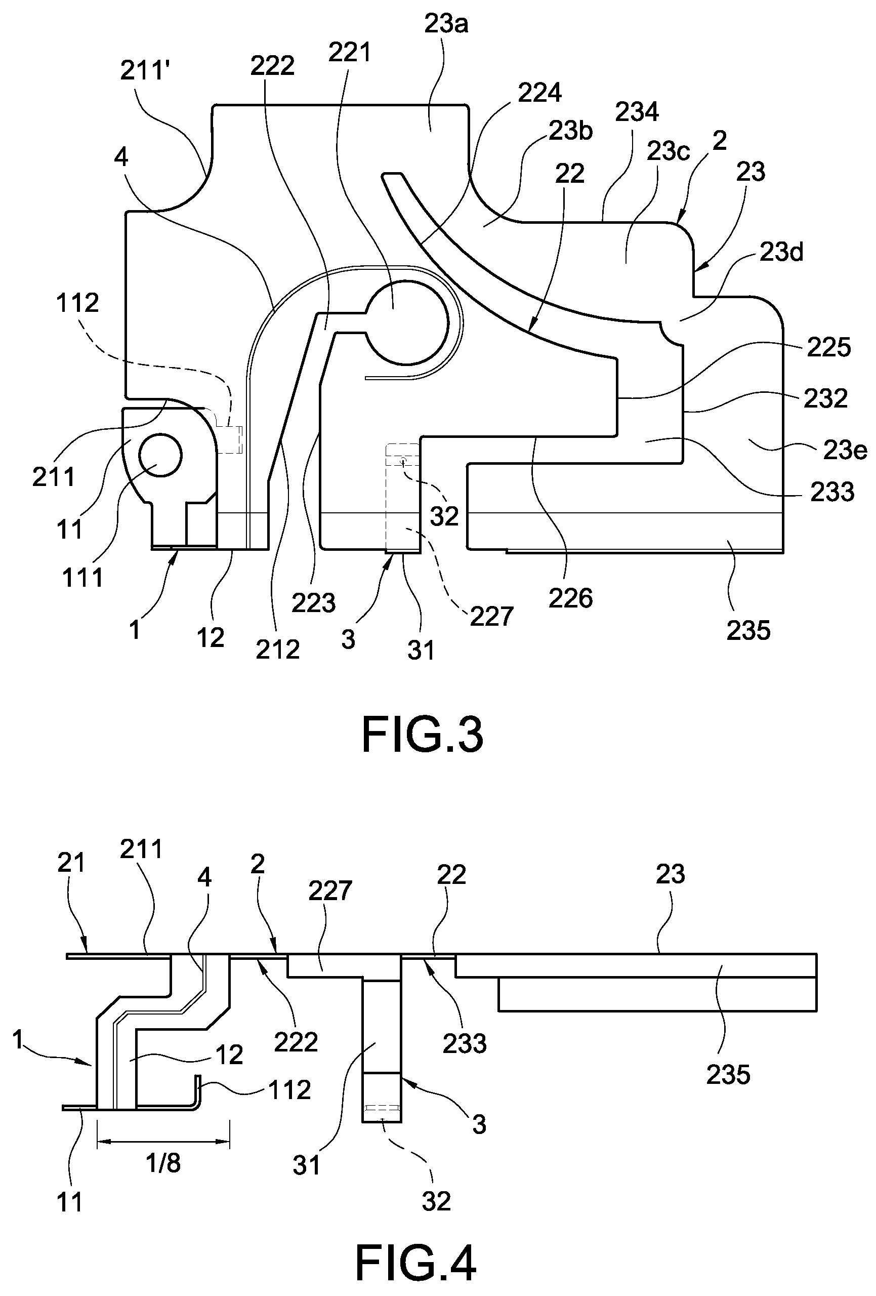
[0024]The ground unit 1 is of plate shape and comprises a ground point 11. A ground hole 111 is defined on the ground point 11 and is fixed to an electronic device (not shown) by a retaining element (not shown). Alternatively, the ground hole 111 is electrically connected to a ground terminal of an electronic device (not shown). A flange 112 is outwardly extended from one side of the ground point 11; and an inverted-L short-line 12 is extended from another end of the ground point 11. The inverted-L short-line 12 is preferably ⅛ resonant wavelength of the multi-band PIFA of the present invention and is electrically connected to the radiating unit 2.

[0025]The radiating unit 2 is of plate shape and comprises a common radiating element 21, a high-frequency (HF) radiating element 22 and a l...


PUM


Abstract

A multi-band planar inverted-F antenna includes a radiating unit, a ground unit and a feeding unit. The radiating unit includes a common radiating element, a high-frequency (HF) radiating element and a low-frequency (LF) radiating element. A quasi U-shaped slot is defined between the HF radiating element and the LF radiating element. The ground unit is electrically connected to one side of the common radiating element. The feeding unit includes a strip electrically connected to one side of the HF radiating element. The ground unit includes a ground point and an inverted-L short-line connected to the ground point at one end thereof. The inverted-L short-line is also electrically connected to the common radiating element at another end thereof. A loop surface current induced by the inverted-L short-line can advantageously enhance bandwidth of the multi-band planar inverted-F antenna at frequencies of interest.

Description

BACKGROUND OF THE INVENTION[0001]1. Field of the Invention[0002]The present invention relates to a multi-band plane inverted-F antenna (PIFA), especially to a multi-band PIFA with an inverted-L short-line to induce a loop surface current, thus enhancing the bandwidth of the multi-band PIFA at multiple frequencies of interest.[0003]2. Description of Prior Art[0004]Modern electronic products for consumer have the trends of compact size and light weight, as manufacture technology and design skill progress. It is also desirable to integrate more versatile functions to the electronic products. Taking wireless communication devices as example, the networking accessing function through wireless application protocol (WAP) and e-mail function are augmented to the original voice function.[0005]Moreover, smart phones with data processing ability and wireless LAN function are also attractive to user these years. The smart phones can provide advanced functions such as mobile TV and business tran...

Claims


Application Information

Patent Timeline
Patent Type & Authority Patents(United States)
IPC IPC(8): H01Q1/38H01Q13/10
CPCH01Q5/371H01Q9/0421
Inventor CHIEN, CHIN-CHENGHO, CHIEN-HSIENLIN, CHIEN-JUNGCHANG, YU-SHENG
Owner FIH (HONG KONG) LTD
Why Eureka
Try Eureka