Faucet sensor mounting assembly

a technology for mounting assemblies and faucets, which is applied in the direction of valves, mechanical devices, engine components, etc., can solve the problems of difficult to ensure the proper assembly of the components, the difficulty of manually assembling the window and the sensor(s) in the proper orientation, and the risk of damage to the sensor and the window from impact, so as to reduce the chance of damage to the window and/or the sensor

Inactive Publication Date: 2009-12-08
KOHLER CO
View PDF18 Cites 40 Cited by
  • Summary
  • Abstract
  • Description
  • Claims
  • Application Information

AI Technical Summary

Benefits of technology

[0008]The present invention provides an automatic faucet with a movable cam assembly for mounting the senor and sensor window inside of the faucet body. The cam has an obliquely angled surface and can be moved up against a spring to provide space for assembling the sensor inside the faucet. Once the sensor is properly positioned, the spring drives the wedge-like cam back down to apply a holding force against the sensor and the window. Back pressure against the sensor or window can be absorbed to some extend by the spring to reduce the chance of damaging the window and / or sensor from impact.
[0013]Thus, with the present invention, the proper installation of the sensor can be made in the tight space inside the faucet quite quickly. Clearances created by manufacturing irregularities or tolerances with respect to the housing will be automatically taken up to create a tighter fit. Further, the assembly does not need any exposed fasteners. Also, while the assembly resists inadvertent or abusive inward force on the window, it also provides some give if the pressure becomes too high to help reduce breakage.

Problems solved by technology

One problem with such automatic faucets pertains to the assembly of the sensors properly within the faucet.
The openings where the window sits and at the bottom of the faucet are usually small and narrow, and thus it is difficult to manually assemble both the window and the sensor(s) in the proper orientation.
Manufacturing clearances and irregularities also make it difficult to ensure that these components are properly assembled.
Another problem has to do with the sensors and windows being susceptible to damage.
Abusive force on these components can render the faucet inoperable.

Method used


Image

  • Faucet sensor mounting assembly
  • Faucet sensor mounting assembly
  • Faucet sensor mounting assembly

Examples


Embodiment Construction

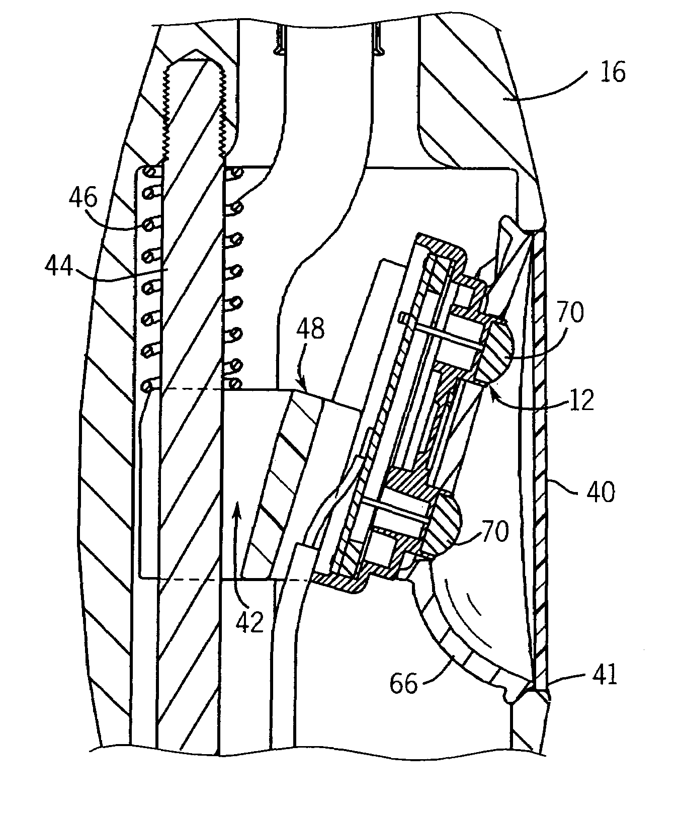
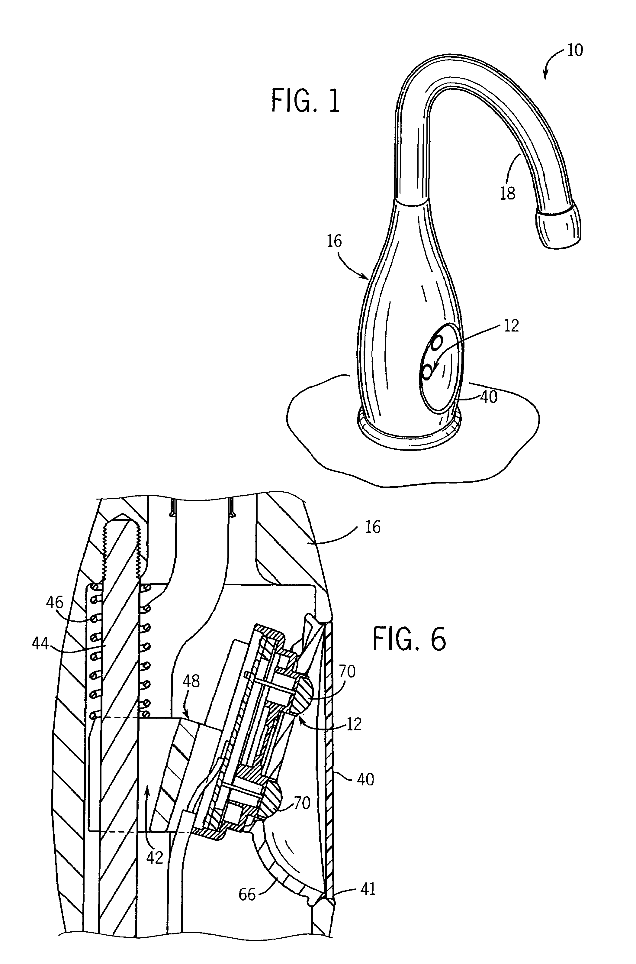
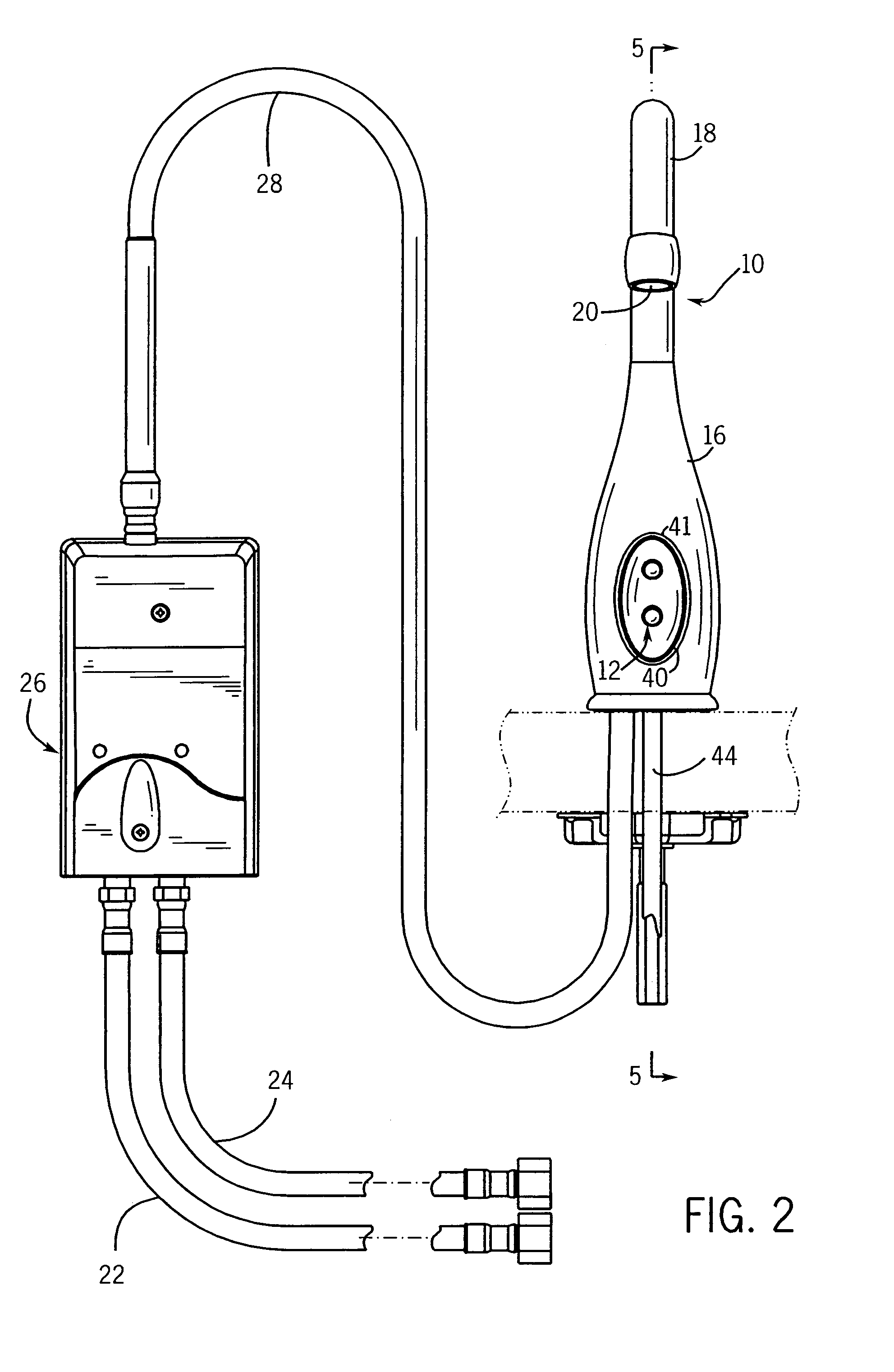
[0021]FIGS. 1 and 2 illustrate an exemplary plumbing fitting in the form of a kitchen faucet 10 having a sensor 12 for detecting the need to open / close a water valve controlling flow from the faucet 10. The faucet 10 has an outer housing or faucet body 16 with hooked spout 18 defining a water passage to a spout outlet 20 where water exits the faucet 10. Hot and cold water lines 22 and 24 coupled to the building plumbing system connected to a mixer / control module 26 where the water flow is combined and regulated to the faucet 10 through line 28. The control module 26 includes an electronically controlled valve 30 (see FIG. 3) and is electrically connected to the sensor 12. The sensor 12 is housed inside the faucet body 16 and senses the area beneath the spout outlet 20. An electrical input signal from the sensor 12 is used by the control module 26 to open and close the valve 30 to either turn on or shut off flow through the faucet 10. For example, when a person place his or her hands...


PUM


Abstract

The present invention provides an automatic faucet with a movable cam assembly for mounting the senor and sensor window inside of the faucet body. The cam has an obliquely angled surface and can be moved up against a spring to provide space for assembling the sensor inside the faucet. Once the sensor is properly positioned, the spring drives the wedge-like cam back down to apply a holding force against the sensor and the window. Back pressure against the sensor or window can be absorbed to some extend by the spring to reduce the chance of damaging the window and / or sensor from impact.

Description

CROSS-REFERENCE TO RELATED APPLICATION[0001]This application claims priority to U.S. provisional patent application Ser. No. 60 / 787,278, filed on Mar. 30, 2006, and entitled “Faucet Sensor Mounting Assembly”.STATEMENT OF FEDERALLY SPONSORED RESEARCH OR DEVELOPMENT[0002]Not applicable.BACKGROUND OF THE INVENTION[0003]The present invention relates to automatic valve control sensors for plumbing fittings. More particularly it relates to an assembly for mounting the sensors inside of the faucet.[0004]Faucets have control valves for regulating the flow of water through the faucet. There can be a single valve that controls mixed hot and cold water flow or dedicated hot and cold water valves. Depending on the number of valves, one or two handles are typically provided for controlling the operation of the valve(s). Other conventional faucets, commonly referred to as “automatic” or “touchless” faucets, although the user to operate the faucet “automatically”. Such automatic faucets typically ...

Claims


Application Information

Patent Timeline
Patent Type & Authority Patents(United States)
IPC IPC(8): E03C1/05
CPCE03C1/057
Inventor ESCHE, JOHN C.
Owner KOHLER CO
Why Eureka
Try Eureka