Electrified handguard

Active Publication Date: 2009-12-08
STEPHEN HINES & MELISSA OCONNELL AS CO TRUSTEES OF THE STEPHEN CHARLES HINES & BARBARA ZINN HINES TRUST
View PDF14 Cites 141 Cited by
  • Summary
  • Abstract
  • Description
  • Claims
  • Application Information

AI Technical Summary

Benefits of technology

[0007]Systems and methods providing an electrified handguard that reduces the ne

Problems solved by technology

The result is a front heavy firearm that

Method used


Image

  • Electrified handguard
  • Electrified handguard
  • Electrified handguard

Examples


Embodiment Construction

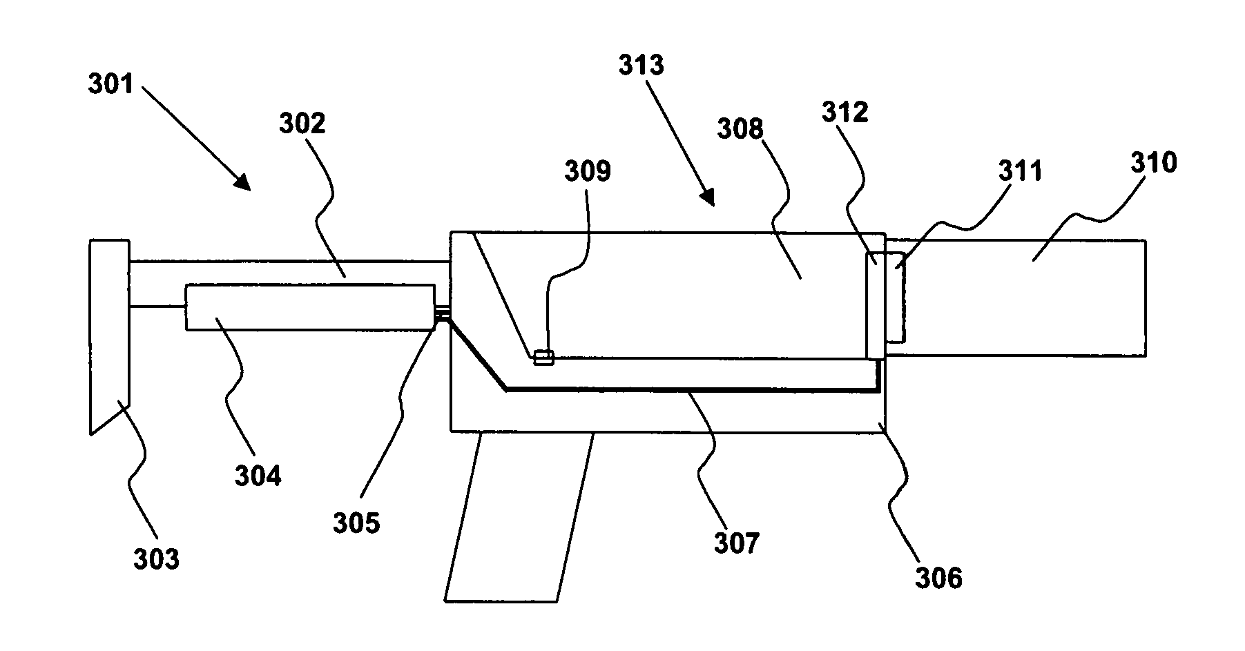
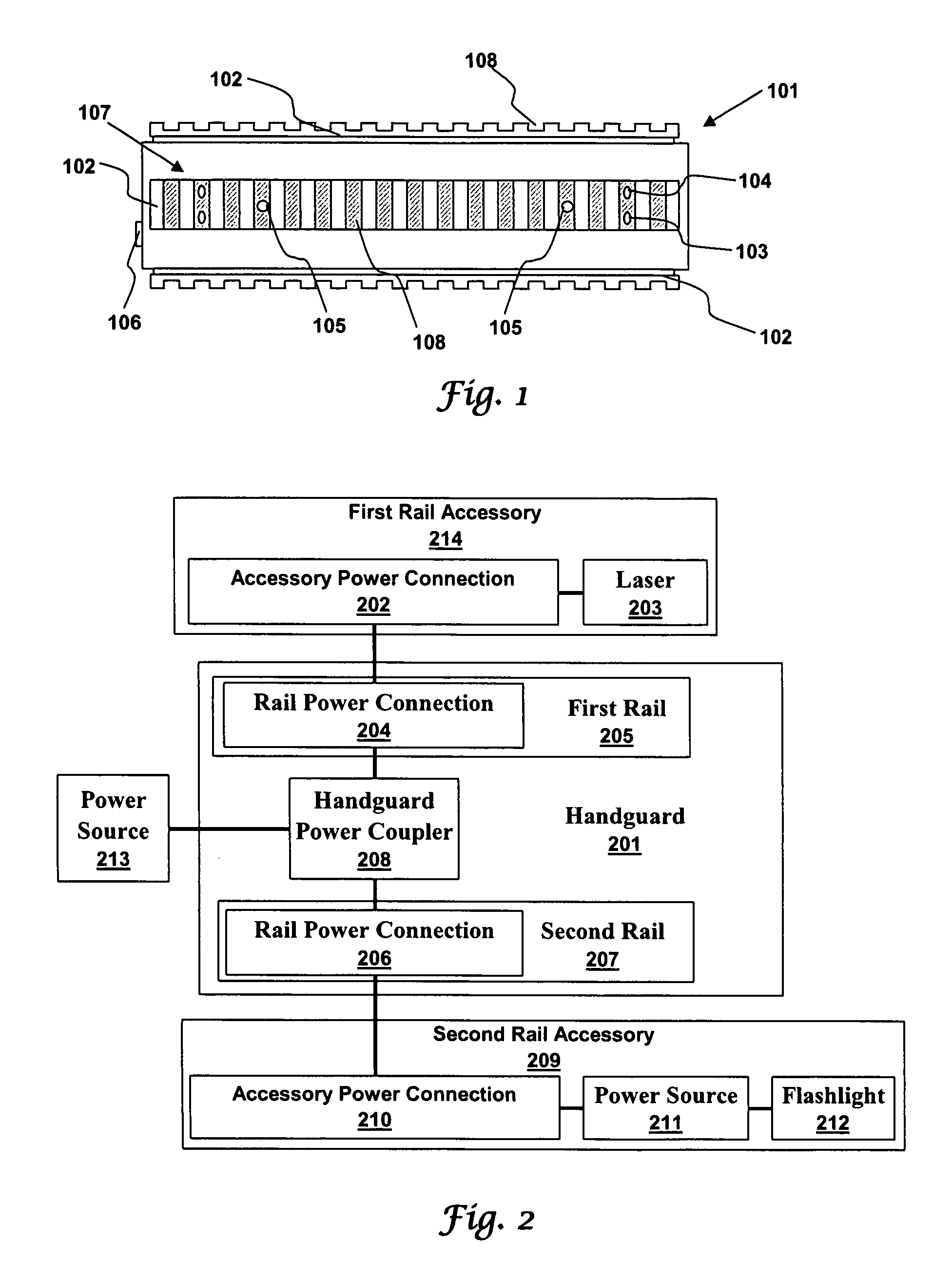
[0021]An electrified handguard for firearms has mounting rails and also supplies electrical power to rail mounted accessories such as flashlights and lasers. A handguard power coupler can receive electrical power from a battery or other power source located elsewhere such as in a buttstock assembly. The electrical power is then routed to power connections in the handguard power coupler. A rail accessory can then be electrically connected to a power connection when it is mechanically attached to a mounting rail.

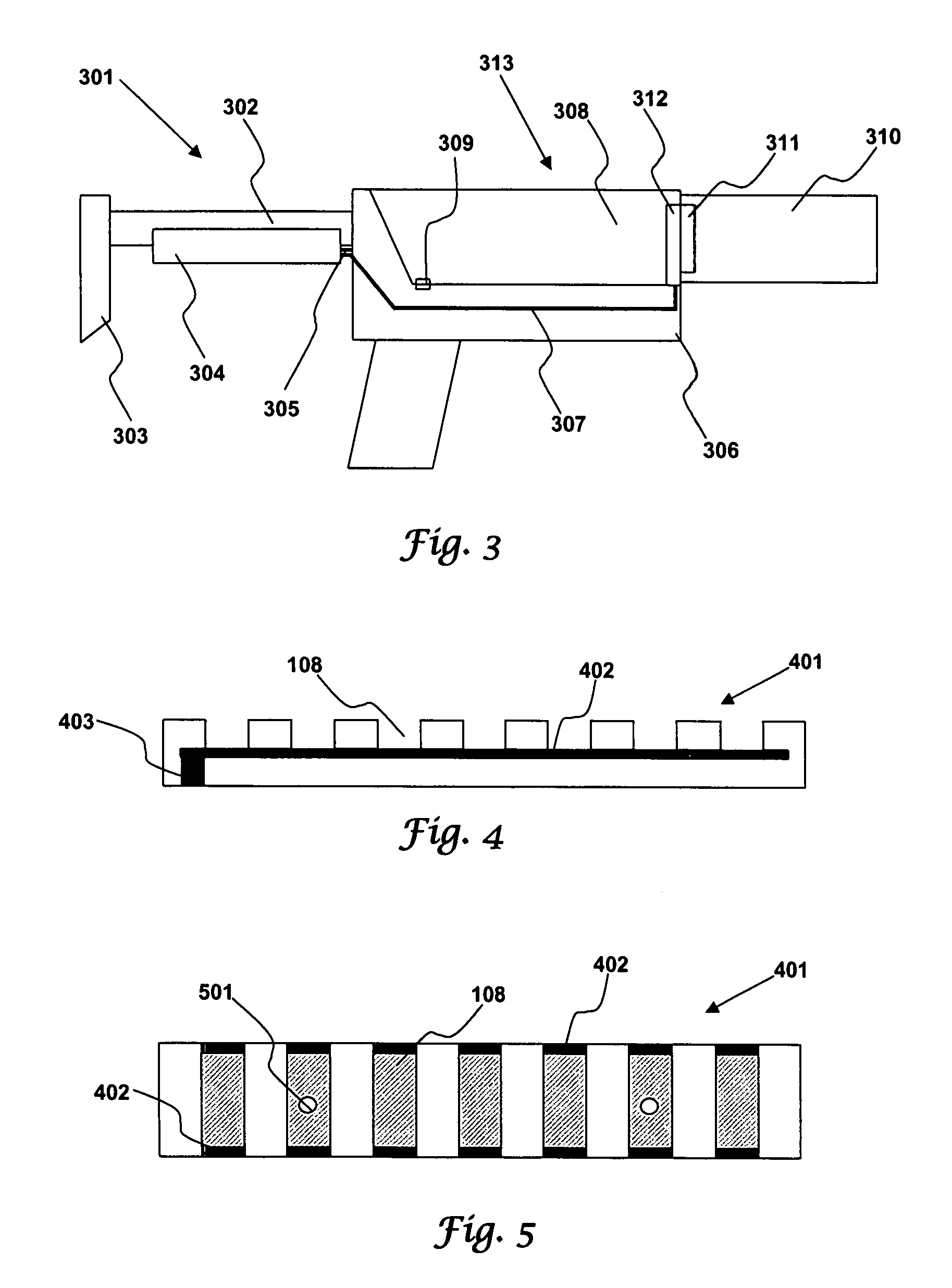
[0022]FIG. 1 illustrates a handguard 101 in accordance with aspects of the embodiments. The handguard is illustrated as having four powered mounting rails 102 of which three are visible. Each powered mounting rail 102 has recoil grooves 108 that help fix accessories in position. Mounting rail power connections 107 are located within the recoil grooves 108 and have a positive electrical contact 103 and a negative electrical contact 104. The handguard is wired to receive electri...


PUM


Abstract

An electrified handguard for firearms has mounting rails and also supplies electrical power to rail mounted accessories such as flashlights and lasers. A handguard power coupler can receive electrical power from a battery or other power source located elsewhere such as in a buttstock assembly. The electrical power is then routed to power connections in the handguard power coupler. A rail accessory can then be electrically connected to a power connection when it is mechanically attached to a mounting rail.

Description

TECHNICAL FIELD[0001]Embodiments relate to the fields of small arms, rifle handguards, carbine handguards, mounting rails, and electric small arms accessories. Embodiments also relate to electrical interconnects, electrical circuits, electrical contacts, and electrical sub assemblies.BACKGROUND[0002]Current small arms use mounting rail systems for attaching accessories to the small arm. For example, M4 and M16 carbines are often fitted with handguards that incorporate up to four Picatinny rails. Picatinny rails are well known mounting rails that meet the specifications contained in MIL-STD-1913 and MIL-STD-1913 Notice 1. Another mounting rail called the Weaver rail is a notoriously well known variation of the Picatinny rail. Battaglia discloses a mounting rail system in U.S. Pat. No. 6,792,711 while Olson discloses another in U.S. Pat. No. 5,826,363.[0003]A number of accessories have been developed to attach to small arms by way of mounting rails. Kim discloses a rail mounted laser ...

Claims


Application Information

Patent Timeline
IPC IPC(8): F41C27/00
CPCF41G11/003F41C23/16
Inventor HINES, STEVE
Owner STEPHEN HINES & MELISSA OCONNELL AS CO TRUSTEES OF THE STEPHEN CHARLES HINES & BARBARA ZINN HINES TRUST
Why Eureka
Try Eureka