

Disassembly method from a water mixing valve of a handle thereof
a technology of water mixing valve and handle, which is applied in the direction of valve operation/release device, mechanical apparatus, transportation and packaging, etc., to achieve the effect of convenient removal
- Summary
- Abstract
- Description
- Claims
- Application Information
AI Technical Summary
Benefits of technology
Problems solved by technology
Method used
Image

Examples
Embodiment Construction
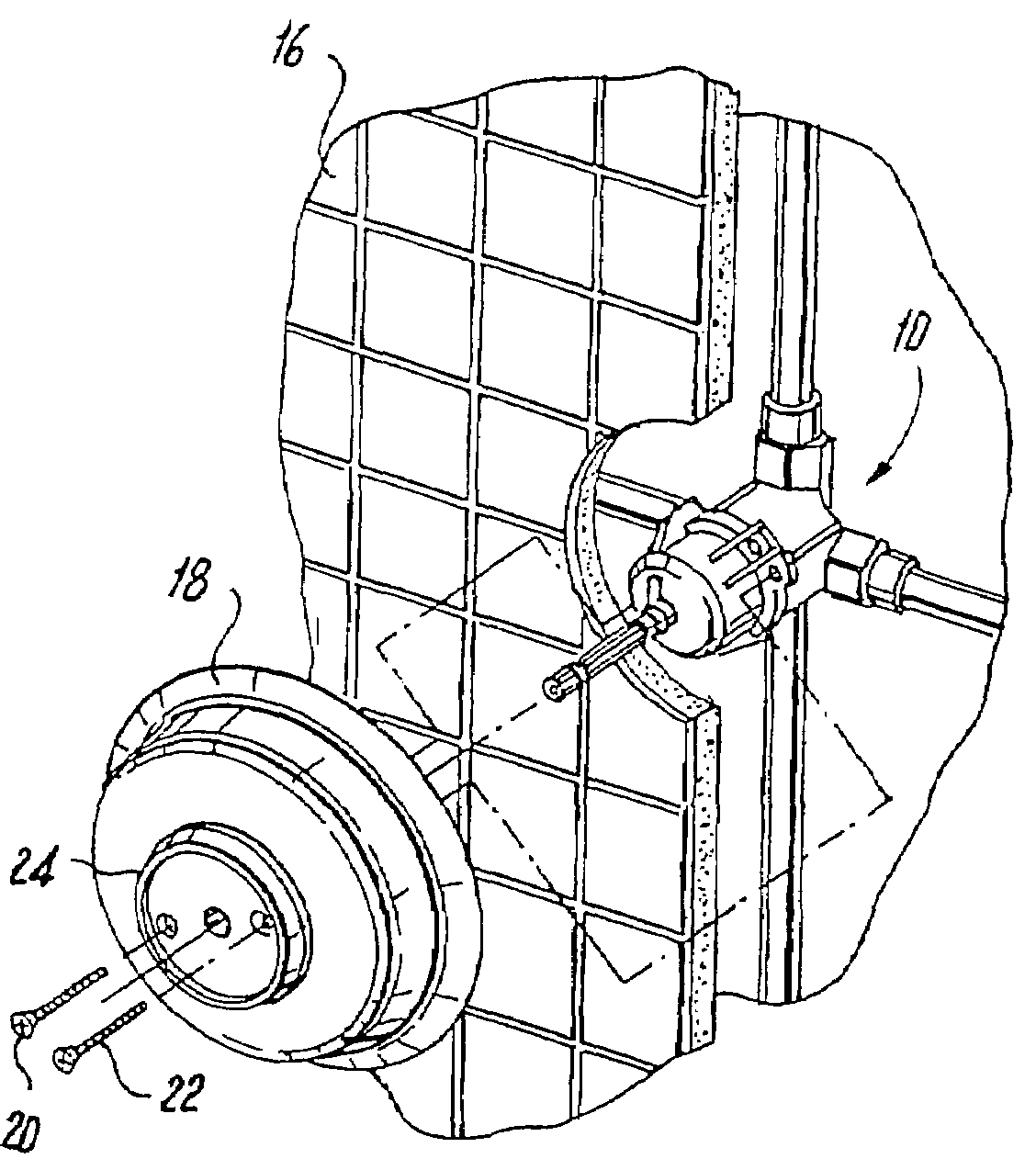
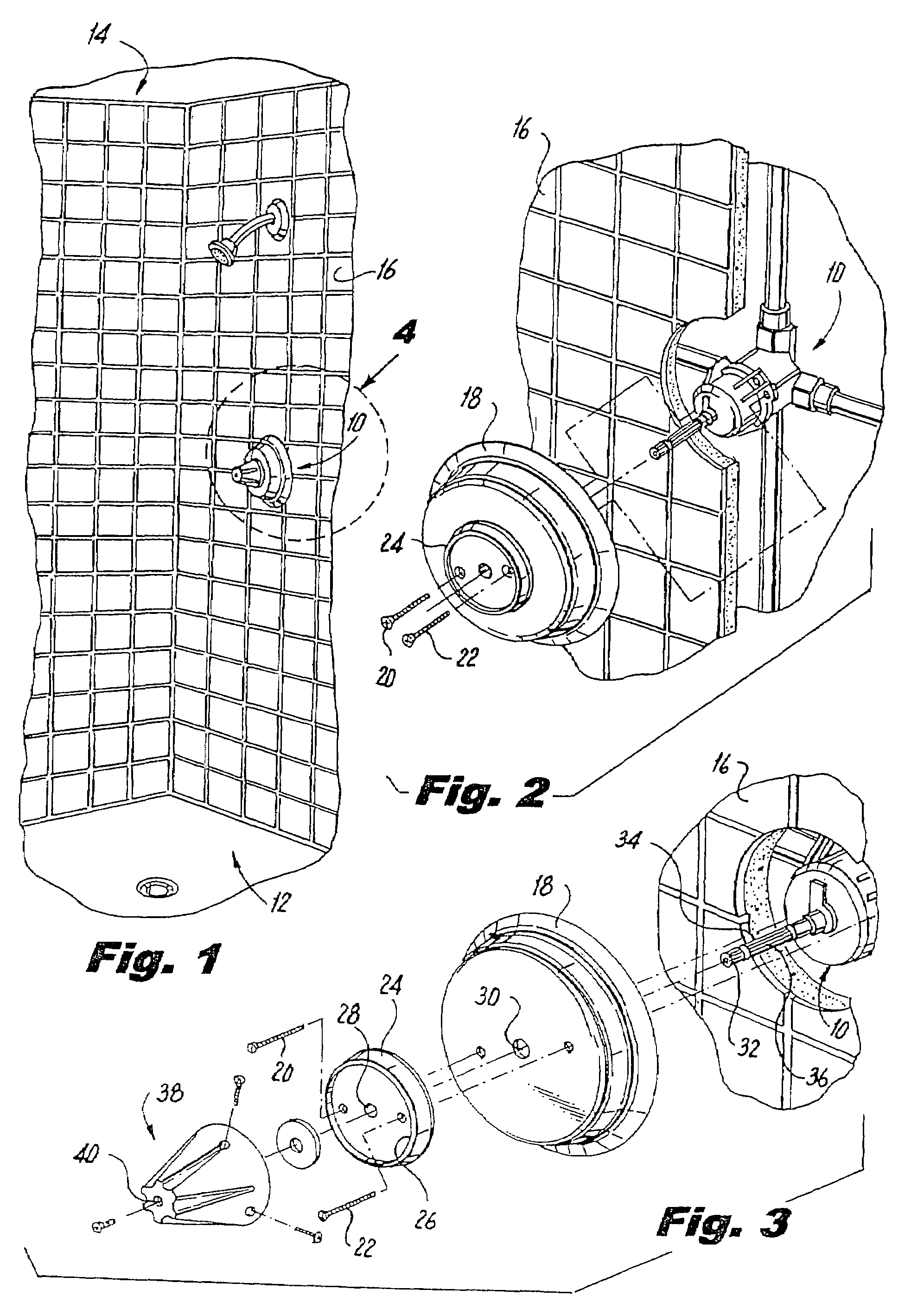
[0014]Shown in the drawings is one of many commercially available water mixing valves, the one preferred being patented by Speakman Co. of Wilmington, Del. under U.S. Pat. No. 3,559,684 and which valve is generally designated 10 and shown in its installed condition operatively disposed to operate the water mixing mode of a stall shower 12 of a psychiatric facility 14, a shower stall wall 16 being a support for an external mounting cover plate 18, with two assembly screws 20 and 22 joining the components 18 and 10.
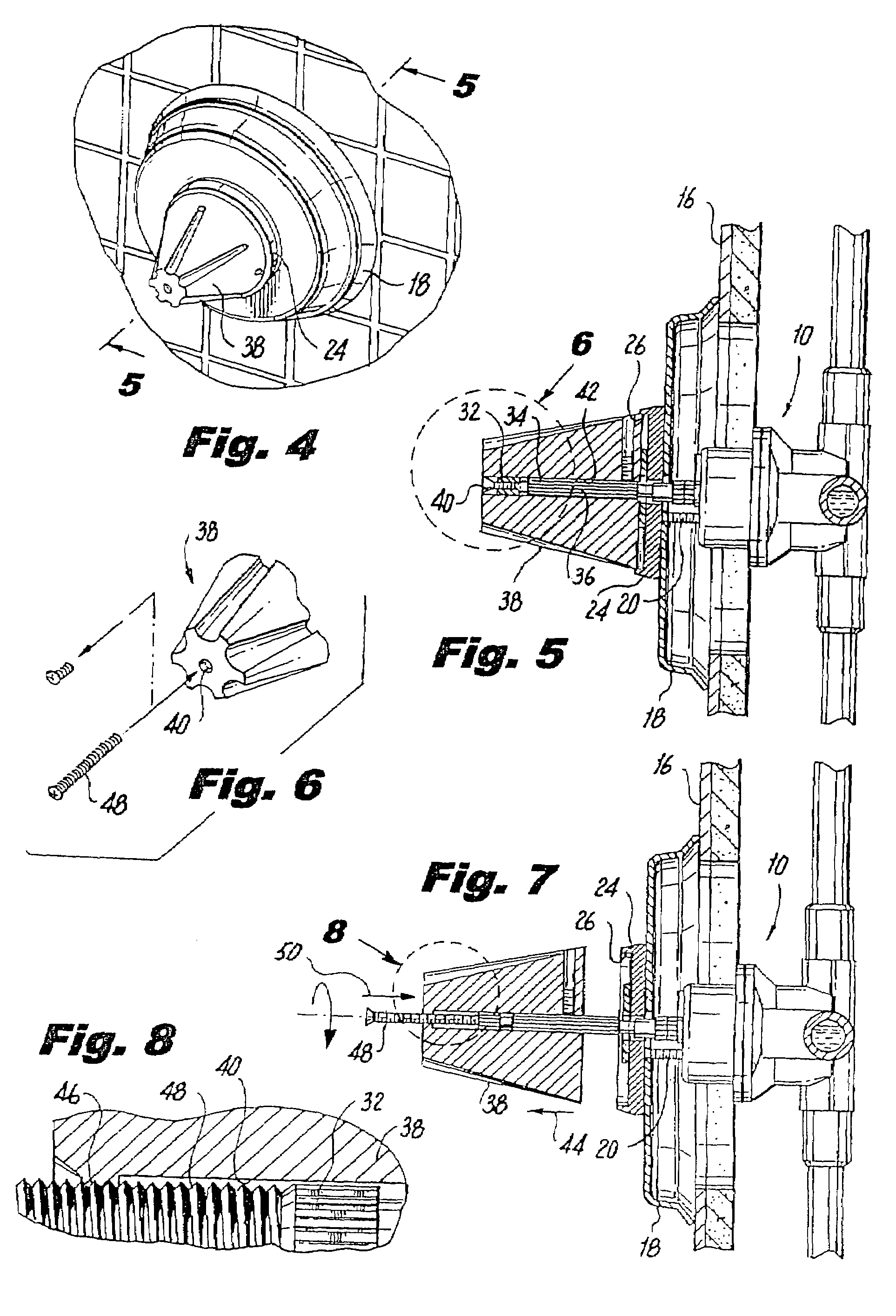
[0015]Disposed in covering relation over the screws 20, 22 is a collar 24 with a circular lip 26 which has a centrally located circular opening 28 in alignment with an underlying central opening 30 of the cover plate 18 and through which openings 28, 30 a free end 32 of a horizontally oriented stem 34 of the valve 10 is projected, said projected stem end 32 being, according to the present invention, having a first embodied splining 36 functional in the disassembling method ...
PUM
 Abstract
Description
Claims
Application Information