Heat exchanger

a heat exchanger and heat exchanger technology, applied in indirect heat exchangers, lighting and heating apparatuses, laminated elements, etc., can solve the problems of difficult dissipation, damage to electronic components, and heat generation of internal electronic components during operation, so as to improve heat exchange efficiency and reduce interference between heated air and cooling air. , the effect of increasing the overall volum

Inactive Publication Date: 2009-12-15
DELTA ELECTRONICS INC
View PDF14 Cites 49 Cited by
  • Summary
  • Abstract
  • Description
  • Claims
  • Application Information

AI Technical Summary

Benefits of technology

[0011]An object of the present invention is to provide a heat exchanger for removing heat accumulated inside a sealed equipment cabinet in enhanced heat exchange efficiency without largely increasing the overall volume thereof, in which the interference between the heated air and the cooling air is minimized.

Problems solved by technology

As known, the internal electronic components may generate heat during operation, which is readily accumulated around the circuit board and difficult to dissipate away.
If the sealed equipment cabinet 1 fails to transfer enough heat to the ambient air, the elevated operating temperature may result in damage of the electronic components, a breakdown of the whole sealed equipment cabinet 1 or reduced operation efficiency.
It is costly and time-consuming to refresh the combination of the heat pipe 17 and the heat sink fins 13.
The interference between the cooled air and the hot air may impair the heat exchange efficiency of the heat exchanger 10.
The interference between the heated air and the cooling air may also impair the heat exchange efficiency of the heat exchanger 10.
The interference between the cooled air and the hot air may impair the heat exchange efficiency of the heat exchanger 20.
The interference between the heated air and the cooling air may also impair the heat exchange efficiency of the heat exchanger 20.
Therefore, the whole volume of the heat exchanger is increased and a large layout space is needed.

Method used


Image

  • Heat exchanger
  • Heat exchanger
  • Heat exchanger

Examples


Embodiment Construction

[0038]The present invention will now be described more specifically with reference to the following embodiments. It is to be noted that the following descriptions of preferred embodiments of this invention are presented herein for purpose of illustration and description only. It is not intended to be exhaustive or to be limited to the precise form disclosed.

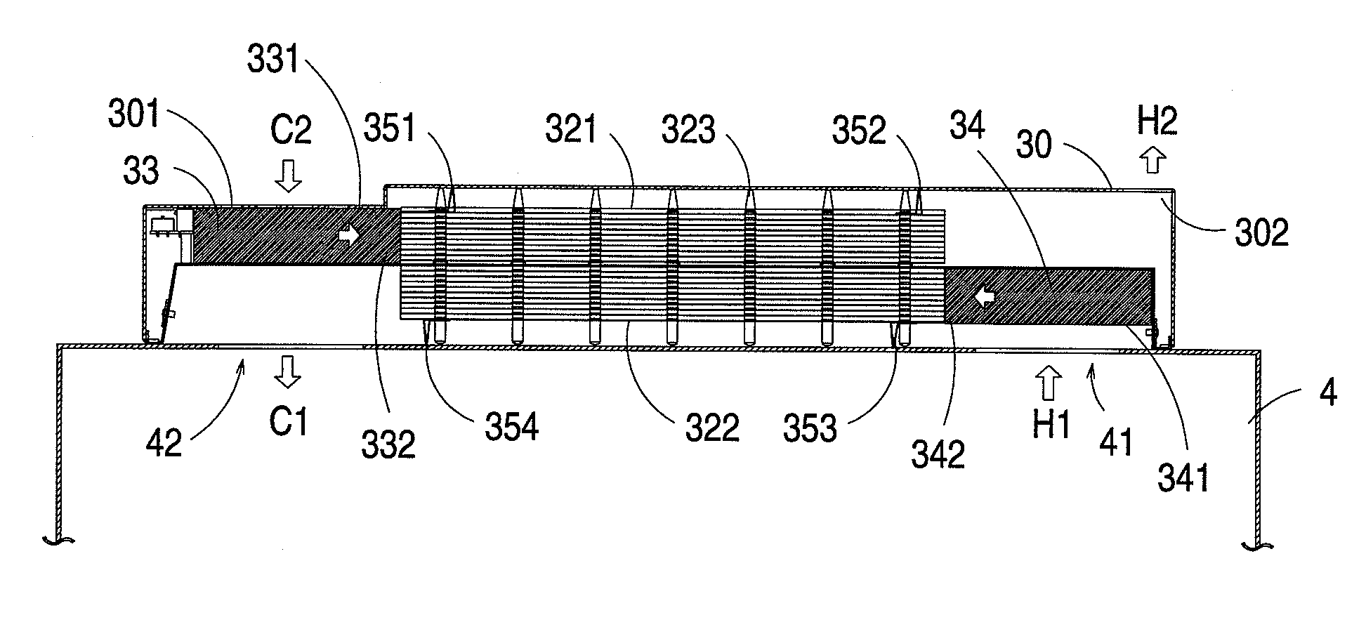
[0039]Referring to FIG. 3, a schematic exploded view of a heat exchanger used in a sealed equipment cabinet according to a preferred embodiment of the present invention is illustrated. The heat exchanger 3 of FIG. 3 principally comprises an external cover 30, a chassis 31, a heat-exchange module 32, a first fan 33, a second fan 34 and several baffle plates 351˜354. Several vent holes 301 and 302 are provided at bilateral sides of the external cover 30, respectively. The chassis 31 is substantially a box with no lid, and comprises a bottom plate 311 and a receptacle 312. The bottom plate 311 of the chassis 31 has a plurality of pe...


PUM


Abstract

A heat exchanger of a sealed equipment cabinet includes a chassis, a heat-exchange module, a first fan and a second fan. The chassis includes a bottom plate having a plurality of first perforations. The heat-exchange module is disposed on the bottom plate, and defines first and second air flow channels at first and second sides of the bottom plate, respectively. The first fan is disposed on the first side of the bottom plate. The second fan is disposed on the second side of the bottom plate.

Description

FIELD OF THE INVENTION[0001]The present invention relates to a heat exchanger, and more particularly to a heat exchanger for removing heat accumulated inside a sealed equipment cabinet.BACKGROUND OF THE INVENTION[0002]Referring to FIG. 1, a schematic view of a conventional sealed equipment cabinet is illustrated. The sealed equipment cabinet 1 is employed for isolating the internal electronic components (not shown) from the adverse environmental conditions such as rain, humidity, dust and pollutants in order to extend the operational lives of the electronic components. As known, the internal electronic components may generate heat during operation, which is readily accumulated around the circuit board and difficult to dissipate away. If the sealed equipment cabinet 1 fails to transfer enough heat to the ambient air, the elevated operating temperature may result in damage of the electronic components, a breakdown of the whole sealed equipment cabinet 1 or reduced operation efficiency...

Claims


Application Information

Patent Timeline
Patent Type & Authority Patents(United States)
IPC IPC(8): H05K7/20
CPCF28D15/0233F28D15/0275F28F3/022H05K7/206
Inventor YANG, TA-JUNG
Owner DELTA ELECTRONICS INC
Why Eureka
Try Eureka