Optical scanning module

a scanning module and optical technology, applied in the field of optical scanning modules, can solve the problems of affecting the scanning quality of image scanners and the failure of image scanners to be slim, and achieve the effect of effectively discharging the heat generated by the lamp tub

Inactive Publication Date: 2007-08-23
PRIMAX ELECTRONICS LTD
View PDF4 Cites 1 Cited by
  • Summary
  • Abstract
  • Description
  • Claims
  • Application Information

AI Technical Summary

Benefits of technology

[0008] It is an object of the present invention to provide an optical scanning module for effectively dissipa

Problems solved by technology

Since the image scanner is developed toward increased resolution and slim volume, the heat generated from the optical scanning module may impair the scanning quality of the image scanne

Method used


Image

  • Optical scanning module
  • Optical scanning module
  • Optical scanning module

Examples


Embodiment Construction

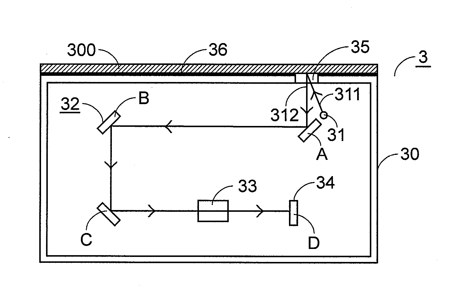
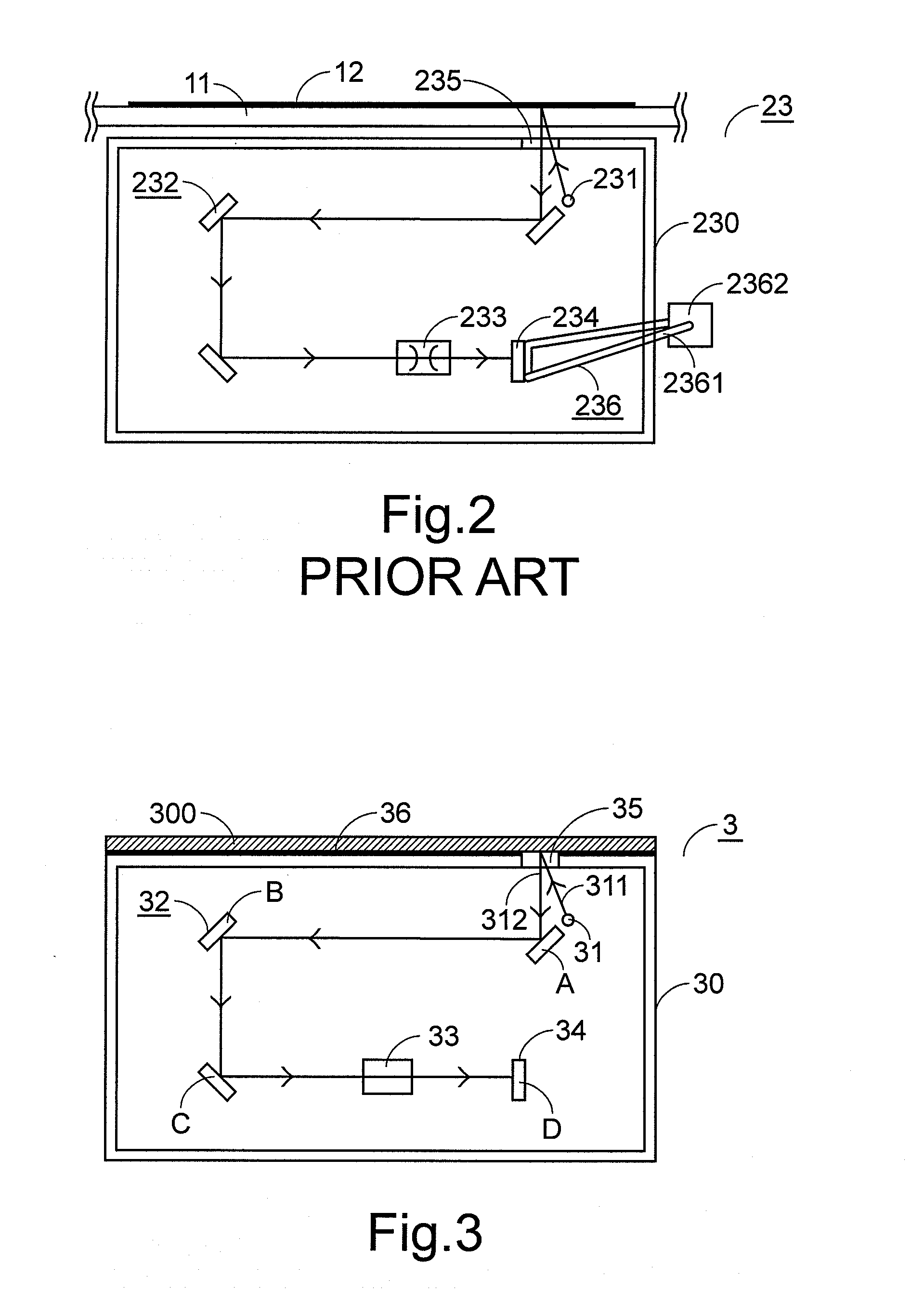
[0022] Referring to FIG. 3, a schematic cross-sectional side view of the internal components of the optical scanning module according to a preferred embodiment of the present invention is illustrated. The optical scanning module 3 of FIG. 3 is applicable to an image scanner (not shown) for scanning an object 300 to be scanned. In the housing 30 of the optical scanning module 3, a light source 31, a reflective mirror set 32, an optical lens 33 and an optical sensor 34 are provided. A light-transmissible window 35 is arranged in the top surface of the housing 30. The operation principles of the related components of the optical scanning module 3 are similar to those described in FIG. 1(b), and are not redundantly described herein.

[0023] An exemplary optical sensor 34 of the optical scanning module 3 is a charge couple device (CCD). Cooperatively, the light source 31 is a cold cathode fluorescent lamp. Since the heat generated from the cold cathode fluorescent lamp is responsible for ...


PUM


Abstract

An optical scanning module includes a housing, a light source and a first heat-dissipating sheet. The light source is disposed inside the housing for emitting a source light to be projected onto the object. The light source includes an electrode wrapped by an electric-insulating and heat-conducting rubber. The first heat-dissipating sheet is arranged on a surface of the housing and in contact with the electric-insulating and heat-conducting rubber.

Description

FIELD OF THE INVENTION [0001] The present invention relates to an optical scanning module, and more particularly to an optical scanning module of an image scanner for scanning an object. BACKGROUND OF THE INVENTION [0002] Flatbed image scanners are widely used in offices or homes for scanning for example documents, photographs or films. The scanned images can be converted into electronic file, which can be directly stored in a computer or further processed by the computer. Referring to FIG. 1(a), a schematic view of a flatbed image scanner is shown. As shown in FIG. 1(a), the flatbed image scanner 1 comprises a transparent platform 11 and an optical scanning module 13. The transparent platform 11 is used for placing thereon the object 12 to be scanned. The optical scanning module 13 is the main component of the flatbed image scanner 1. After the object 12 is placed on the transparent platform 11, the optical scanning module 13 is moved along the scanning direction so as to scan the ...

Claims


Application Information

Patent Timeline
IPC IPC(8): G06K7/10
CPCH04N1/1017H04N1/00989
Inventor CHEN, HSI-YUCHEN, KUAN-YANG
Owner PRIMAX ELECTRONICS LTD
Why Eureka
Try Eureka