
Display

a technology for display and brackets, applied in the field of display, can solve the problems of disadvantageous insufficient strength of mounting brackets, etc., and achieve the effect of improving the strength of components of mounting brackets and stable placemen

Inactive Publication Date: 2009-12-15
FUNAI ELECTRIC CO LTD
View PDF11 Cites 8 Cited by
  • Summary
  • Abstract
  • Description
  • Claims
  • Application Information

AI Technical Summary

Benefits of technology

[0015]The present invention has been proposed in order to solve the aforementioned problems, and an object of the present invention is to provide a display, in which a display screen portion is reliably anteroposteriorly positioned in a working step for mounting the display screen portion on a stand, the display screen portion can be stably placed on the stand, and component strength of a mounting bracket can be improved.

Problems solved by technology

Therefore, the mounting bracket is disadvantageously insufficient in strength.
When the heavy display screen portion (display body) including metal components etc. and having a horizontally long shape is mounted on the stand, therefore, the former cannot be stably placed (temporarily placed) on the latter.
Therefore, the display screen portion (display body) cannot be reliably horizontally positioned when mounted on the stand unit.
Therefore, the mounting bracket is disadvantageously insufficient in strength.

Method used


Image

  • Display
  • Display
  • Display

Examples


Embodiment Construction

[0046]An embodiment of the present invention is now described with reference to the drawings.

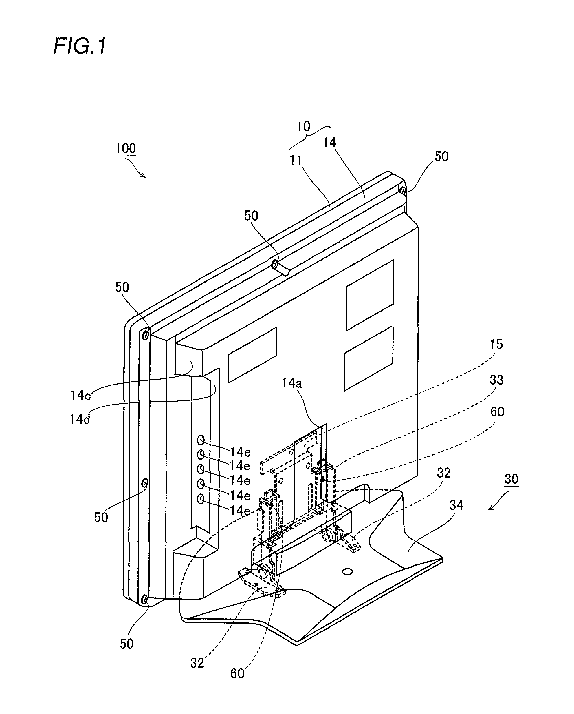
[0047]The structure of a liquid crystal display 100 according to the embodiment of the present invention is described with reference to FIGS. 1 to 8. This embodiment of the present invention is applied to the liquid crystal display 100 employed as an exemplary display.

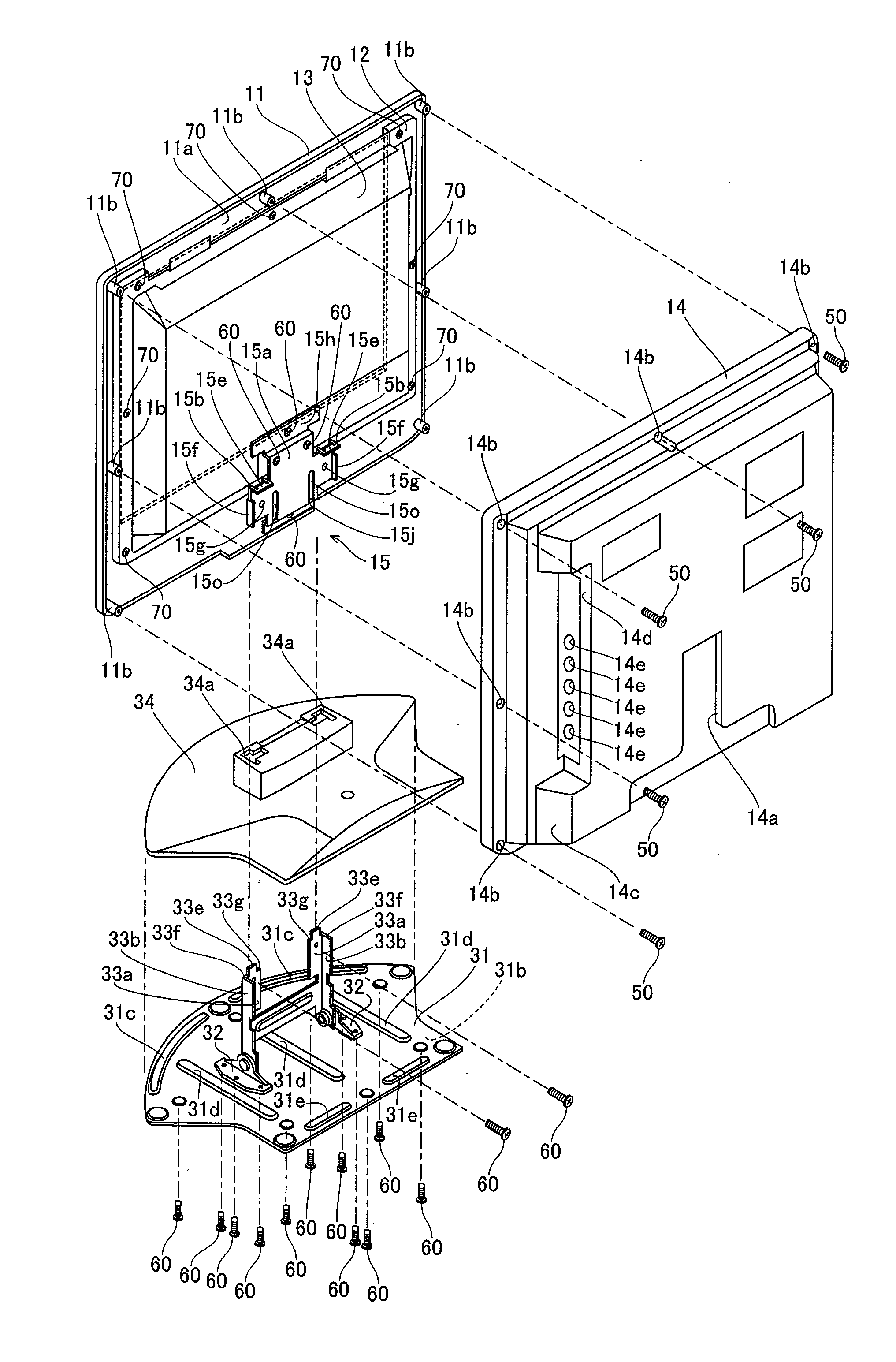
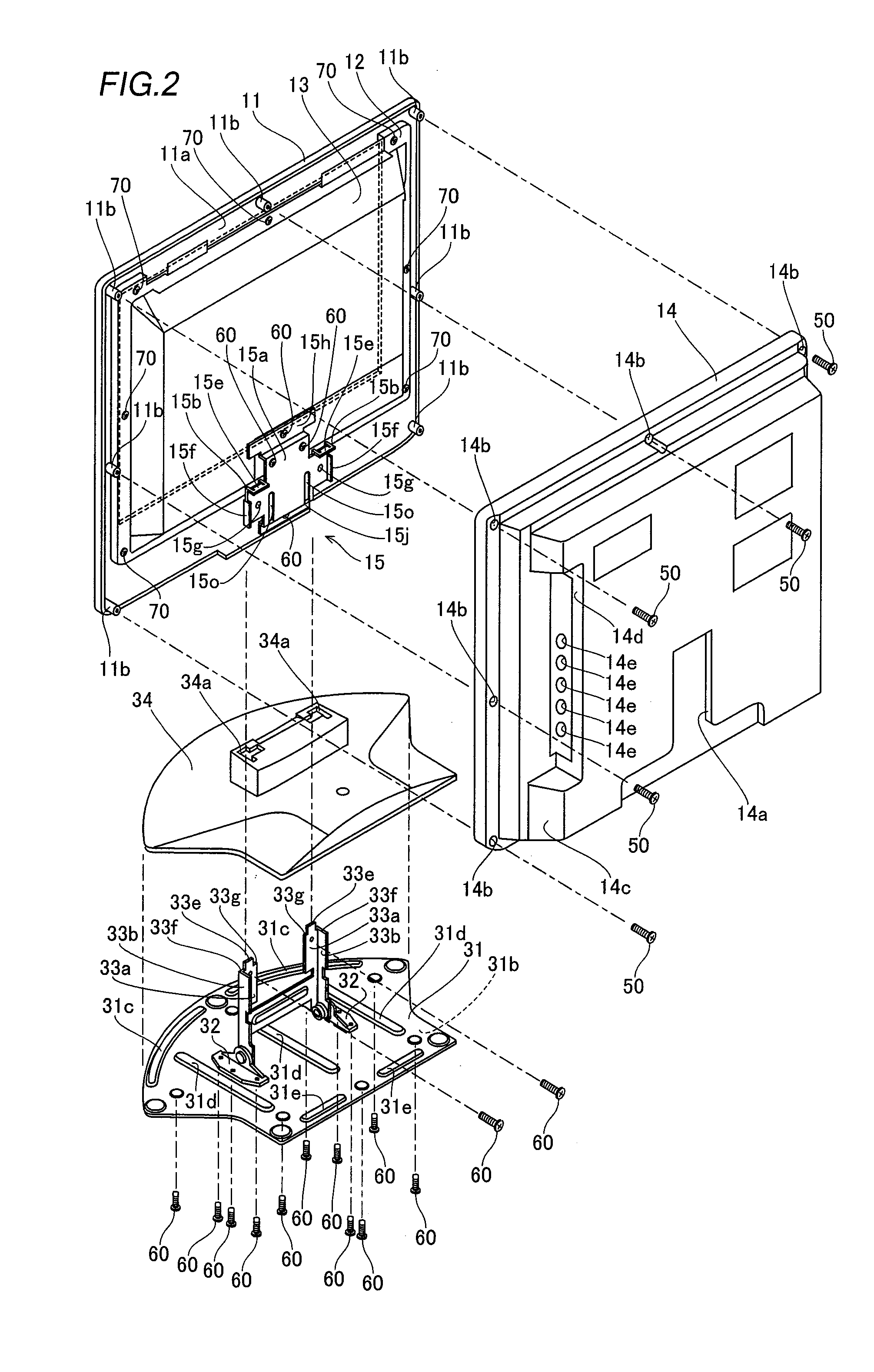
[0048]The liquid crystal display 100 according to the embodiment of the present invention comprises a display body 10 and a stand 30 capable of anteroposteriorly inclining the display body 10 by a prescribed angle, as shown in FIG. 1. The display body 10 is constituted of a front cabinet 11 of resin, a liquid crystal module 13 formed by mounting a liquid crystal panel (not shown) on a chassis 12 of metal and a rear cabinet 14 of resin, as shown in FIGS. 1 and 2. A bracket member 15 of sheet metal is mounted on a lower portion of the display body 10 with screws 60 to extend over the liquid crystal module 13 and the front cabinet...


PUM


Abstract

This display includes a bracket member mounted on a display screen portion and a stand member including a pair of support portions, having an L-shaped cross section, mounted with the bracket member slid from above, while the bracket member includes a pair of first regulating portions regulating downward movement of the bracket member with respect to the stand member by coming into contact with the pair of support portions of the stand member respectively and a pair of second regulating portions regulating anteroposterior movement of the bracket member with respect to the stand member by anteroposteriorly holding the pair of support portions of the stand member respectively.

Description

BACKGROUND OF THE INVENTION[0001]1. Field of the Invention[0002]The present invention relates to a display, and more particularly, it relates to a display comprising a display screen portion.[0003]2. Description of the Background Art[0004]A display comprising a display screen portion is known in general, as disclosed in each of Japanese Patent Laying-Open Nos. 2006-91713 and 2005-221823, Japanese Utility Model Registration Nos. 3116087 and 3107250 and Japanese Patent Laying-Open No. 2004-118191, for example.[0005]The aforementioned Japanese Patent Laying-Open No. 2006-91713 discloses a display comprising a display screen portion (display body) having a chassis therein, a stand provided with a mounting bracket rotatably supporting the display screen portion (display body) from the rear surface thereof and a coupling piece held between the display screen portion (display body) and the mounting bracket. This display is so formed as to vertically position the mounting bracket by fitting...

Claims


Application Information

Patent Timeline
Patent Type & Authority Patents(United States)
IPC IPC(8): F16M11/00
CPCF16M11/10G06F1/1601G06F2200/1612F16M2200/08
Inventor MAKINO, KATSUHIKO
Owner FUNAI ELECTRIC CO LTD
Learn More