Combined spectacle lens, auxiliary lens, and method of edging lenses

a technology of edging lens and spectacle lens, which is applied in the direction of optics, instruments, optical parts, etc., can solve the problems of not being designed to be optimal for different applications, increasing costs, and inability to obtain optimal optical performance for different applications in one design, so as to achieve convenient change, secure assembly accuracy, and easy change of design type or the like of the basic lens

Inactive Publication Date: 2009-12-15
HOYA LENS MFG PHILIPPINES
View PDF22 Cites 5 Cited by
  • Summary
  • Abstract
  • Description
  • Claims
  • Application Information

AI Technical Summary

Benefits of technology

[0010]It is a first advantage of the invention to provide a combined spectacle lens which can change a design type of a progressive-power lens.
[0011]The sub-lenses used in the spectacle glasses of a front-hanging type described above are sunglasses for adjusting or polarizing light, or monofocal lenses for presbyopia eyes, and hence are intended to be worn in addition to the existing spectacle lenses. Therefore, positional accuracy of overlapped lenses is not very much necessary, and hence the overlapping position of both lenses must simply be approximate. In contrast, the case of the combined spectacle lens in which the design type of the progressive-power lens can easily be changed is fundamentally different from the case of the spectacle glasses of the front-hanging type, and the basic lens and the auxiliary lens both have a progressive-power surface, and hence a predetermined optical performance cannot be obtained unless these lenses are overlapped in an accurate positional relation when they are actually used.
[0012]It is a second advantage of the invention to provide a combined spectacle lens in which a basic lens and an auxiliary lens of the combined spectacle lens composed of a basic lens having a progressive-power and an auxiliary lens having a power to convert the design type of the basic lens can be combined in an accurate positional relation.
[0013]It is a third advantage of the invention is to provide the auxiliary lens which can change the design type or the like of the basic lens easily by being combined with the basic lens.
[0014]An assembly error when assembling the basic lens and the auxiliary lens for use may occur according to edging for machining the lens into a contour to be accommodated in the spectacle glass frame, and hence the assembly accuracy may not be secured depending on an edging accuracy.
[0015]In view of such a circumstance, it is a fourth advantage of the invention to provide a method of edging a combined spectacle lens which can secure assembly accuracy of the combined spectacle lens including a basic lens having a progressive power and an auxiliary lens having a power to convert the design type or the like of the basic lens.

Problems solved by technology

In this manner, the optimal optical performance for different applications cannot be obtained in one design.
However, in this circumstance, it is necessary to purchase lenses of different designs, and also to purchase the spectacle glass frames for each type of lenses, and hence the cost is increased.
However, it simply provides a monofocal view, and is not designed to be optimal for different applications.
In contrast, the case of the combined spectacle lens in which the design type of the progressive-power lens can easily be changed is fundamentally different from the case of the spectacle glasses of the front-hanging type, and the basic lens and the auxiliary lens both have a progressive-power surface, and hence a predetermined optical performance cannot be obtained unless these lenses are overlapped in an accurate positional relation when they are actually used.
An assembly error when assembling the basic lens and the auxiliary lens for use may occur according to edging for machining the lens into a contour to be accommodated in the spectacle glass frame, and hence the assembly accuracy may not be secured depending on an edging accuracy.
If the basic lens and the auxiliary lens are edged separately, when they are combined with reference to their contours, respective edging errors are added, and hence positioning accuracy between the basic lens and the auxiliary lens may not be secured.

Method used


Image

  • Combined spectacle lens, auxiliary lens, and method of edging lenses
  • Combined spectacle lens, auxiliary lens, and method of edging lenses
  • Combined spectacle lens, auxiliary lens, and method of edging lenses

Examples


Embodiment Construction

[0054]An embodiment of a combined spectacle lens, an auxiliary lens, and a method of edging the combined spectacle lens of the invention will be described below. However, the invention is not limited to the embodiment shown below.

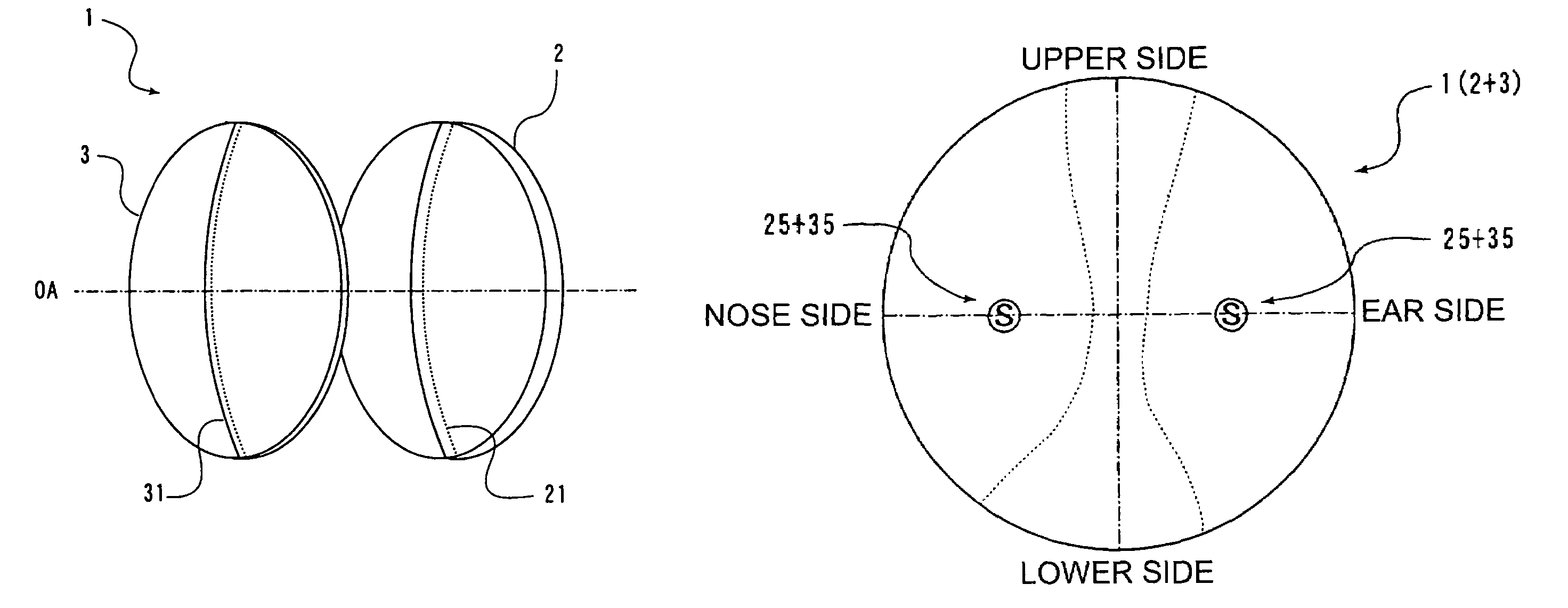
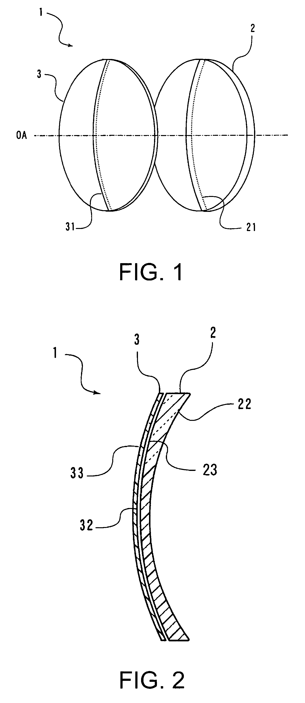
[0055]As shown in a perspective view in FIG. 1, a combined spectacle lens 1 of the invention includes a basic lens 2 which is a progressive-power lens and an auxiliary lens 3 used only for an application to be combined with the basic lens 2 and has a power to convert a design type of the basic lens 2. The basic lens 2 and the auxiliary lens 3 are used by being combined so as to align a principal meridian 21 of the basic lens 2 and a principal fixation line 31 of the auxiliary lens 3 to be aligned with the principal meridian 21, and align optical axes OA of the basic lens 2 and the auxiliary lens 3.

[0056]As shown in a cross-section of the combined spectacle lens 1 in FIG. 2, a combination mode in which the basic lens 2 is arranged on an eyeball side and the ...


PUM


Abstract

A combined spectacle lens including a combination of a basic lens and an auxiliary lens, the basic lens formed with a progressive-power surface having a first power portion having a power for viewing an object at a predetermined distance, a second power portion having a power different from that in the first power portion, and a progressive portion in which the power is progressively changed from the first power portion to the second power portion on either one or both of refractive surfaces on an object side and an eyeball side, wherein a resultant power obtained by combining a basic lens power of the basic lens and an auxiliary lens power of the auxiliary lens is partly or entirely different from that of the basic lens power.

Description

BACKGROUND[0001]1. Technical Field[0002]The present invention relates mainly to a combined spectacle lens having a progressive power for a person having presbyopia eyes with low amplitude of accomodation and an auxiliary lens used for the combined spectacle lens, and a method of edging the lenses.[0003]2. Related Art[0004]A progressive-power lens is used mainly as a vision corrective lens for a person having presbyopia eyes with low amplitude of accomodation, and is a lens in which a power is changed continuously from a power required for viewing an object at a distance or an intermediate distance to a power required for viewing an object nearby on one piece of lens without no boundary so that it has a fashionable looking.[0005]Optical performance of the progressive-power lens basically depend on a progressive corridor length which corresponds to a distance on a principal meridian of a progressive portion in which the power is continuously changed and an addition power which is a di...

Claims


Application Information

Patent Timeline
Patent Type & Authority Patents(United States)
IPC IPC(8): G02C7/06G02C7/08
CPCG02C7/061G02C7/086G02C7/063G02C2202/16G02C7/06
Inventor SHINOHARA, TOSHIHIDEKAGA, TADASHI
Owner HOYA LENS MFG PHILIPPINES
Why Eureka
Try Eureka