Method and system for modifying heavy oil through hydrodynamic cavitation
A hydraulic cavitation and heavy oil technology, which is applied in the petroleum industry, refining hydrocarbon oil, etc., can solve the problems of low saturated steam pressure, high viscosity and high flow velocity of heavy oil, and meet the upgrading requirements, save energy consumption and applicability Good results
- Summary
- Abstract
- Description
- Claims
- Application Information
AI Technical Summary
Problems solved by technology
Method used
Image
Examples
Embodiment 1
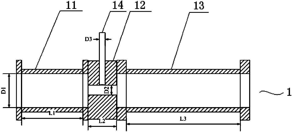
[0038] Such as figure 1 As shown, the hydraulic cavitation device 1 of this embodiment includes a heavy oil inlet section 11, a throat section 12 and a stabilizing section 13 arranged in sequence. area, the throat section 12 is respectively connected with the heavy oil inlet section 11 and the stabilizing section 13 and communicated axially, and an auxiliary agent inlet section 14 communicating with the throat section 12 is arranged radially on the throat section 12 . Specifically, the heavy oil inlet section 11, the throat section 12 and the stabilizing section 13 are all cylindrical and have axial through holes, and flanges are arranged at both ends of the heavy oil inlet section 11 and the stabilizing section 13, and the throat section 12 can be provided with threaded holes, and the heavy oil inlet section 11, the throat section 12 and the stabilizing section 13 can be fixed through flange screw connections, and the through holes of each section are axially connected, and e...
Embodiment 2
[0044] Adopt the hydraulic cavitation device of embodiment 1 to carry out heavy oil reforming, difference is: D1 is 40mm, D2 / D1 is 0.2, D3 / D2 is 0.3, L1 / D1 is 1, L2 / D2 is 1.5, L3 / D1 is 5. The inner diameter of the stabilizing section is 40mm, and the heavy oil inlet section, the throat section and the stabilizing section are integrally formed.
[0045] After the heavy oil is heated to about 60°C and pressurized to about 5.1MPa by a high-pressure pump, it is sent to the heavy oil inlet section of the hydraulic cavitation device. When the heavy oil reaches the throat section, trimethylamine (cavitation aid) is passed through the auxiliary agent inlet. The trimethylamine is vaporized in the stage suction hydraulic cavitation device, and the heavy oil and trimethylamine undergo hydrodynamic cavitation in the stable stage, wherein the addition of trimethylamine is controlled so that the weight ratio of heavy oil and trimethylamine is 100:5; hydraulic cavitation After the product is...
Embodiment 3
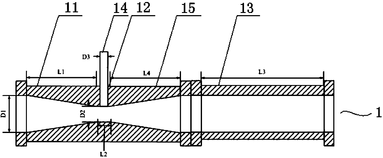
[0047] Such as figure 2 As shown, the hydraulic cavitation device 1 of this embodiment includes a heavy oil inlet section 11, a throat section 12, an expanding section 15, and a stabilizing section 13 arranged in sequence. The heavy oil inlet section 11, the throat section 12, and the expanding section 15 are integrally formed, and the heavy oil The inlet section 11 and the enlarged section 15 all have a trumpet-shaped through hole, and the small ends of the trumpet-shaped through-hole are all arranged towards the throat section 12, and the throat section 12 and the enlarged section 15 are all cylindrical and have a through hole, and the trumpet-shaped through hole The diameters of the small ends are the same as the inner diameter of the throat section 12, and the through holes of the heavy oil inlet section 11, the throat section 12, and the expansion section 15 are arranged coaxially; An auxiliary agent inlet section 14 communicating with the throat section 12 is arranged r...
PUM
| Property | Measurement | Unit |
|---|---|---|
| Boiling point | aaaaa | aaaaa |
| Density | aaaaa | aaaaa |
Abstract
Description
Claims
Application Information
 - R&D
- Intellectual Property
- Life Sciences
- Materials
- Tech Scout
- Unparalleled Data Quality
- Higher Quality Content
- 60% Fewer Hallucinations
Browse by: Latest US Patents, China's latest patents, Technical Efficacy Thesaurus, Application Domain, Technology Topic, Popular Technical Reports.
© 2025 PatSnap. All rights reserved.Legal|Privacy policy|Modern Slavery Act Transparency Statement|Sitemap|About US| Contact US: help@patsnap.com


