Optical calculation optical coherence imaging system with high signal-to-noise ratio

An optical coherent imaging, high signal-to-noise ratio technology, applied in the field of biomedical photonics, to achieve the effect of improving signal-to-noise ratio, reducing loss, and reducing detection bandwidth

Active Publication Date: 2018-09-25
TSINGHUA UNIV
View PDF1 Cites 3 Cited by
  • Summary
  • Abstract
  • Description
  • Claims
  • Application Information

AI Technical Summary

Problems solved by technology

No matter how fast the imaging speed is, if the image signal is submerged in noise, there will be many limitations in practical use

Method used


Image

  • Optical calculation optical coherence imaging system with high signal-to-noise ratio
  • Optical calculation optical coherence imaging system with high signal-to-noise ratio
  • Optical calculation optical coherence imaging system with high signal-to-noise ratio

Examples


Embodiment 1

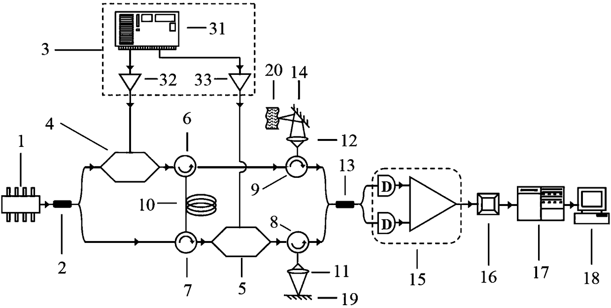
[0020] Such as figure 1 As shown, the optical computing optical coherent imaging system provided in this embodiment includes an optical computing system and an image display system. The optical computing system includes a broadband light source 1, a first coupler 2, a signal generating device 3, a first optical phase modulator 4, a second optical phase modulator 5, first to fourth circulators 6 to 9, a dispersion device 10, A first focusing lens 11 , a second focusing lens 12 , a second coupler 13 , a two-dimensional scanning system 14 and a mirror 19 , and the image display system includes a balanced detector 15 , a filter 16 , a demodulator 17 and a computer 18 . Wherein, the first optical phase modulator 4 generates a shape of cos(at 2 ) signal to drive, the second optical phase modulator 5 generates a shape of cos(at 2 +2πf 0 t) The signal is used for driving, and the dispersion device 10 of this embodiment may use a dispersion fiber.

[0021] The DC broadband light em...

Embodiment 2

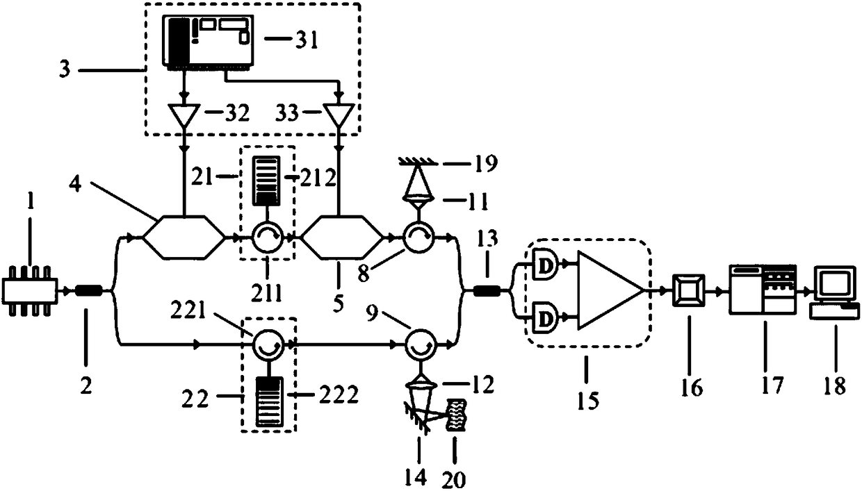
[0026] Such as figure 2 As shown, the optical path structure and optical path devices of this embodiment are basically the same as those of Embodiment 1. The difference is that in Embodiment 1, a dispersion device 10 is used for both reference light and measurement light. In this embodiment, reference light and measurement light use their respective The two dispersive devices have the same structure and function. The first dispersive device 21 uses a circulator 211 and a fiber Bragg grating 212, and the second dispersive device 22 uses a circulator 221 and a fiber Bragg grating 222. The specific process of optical path propagation in this embodiment is as follows:

[0027] The DC broadband light emitted by the broadband light source 1 is divided into reference light and measurement light by the first coupler 2;

[0028] The reference light is sent to the first optical phase modulator 4 for modulation and then sent to the circulator 211, the optical signal emitted by the circ...


PUM


Abstract

The invention relates to an optical calculation optical coherence imaging system with high signal-to-noise ratio. The optical calculation optical coherence imaging system is characterized in that direct current broadband light emitted by a broadband light source is split into reference light and measurement light by a first coupler; the reference light is emitted to a first optical phase modulation device and is modulated, the modulated light is emitted to a dispersion device, the light passing through the dispersion device is emitted to a second optical phase modulation device and is modulated again, the modulated light is emitted to a reflection mirror by a focusing lens, then returns along the original optical path, and is emitted to a second coupler; the measurement light enters the dispersion device, the light emitted by the dispersion device enters a two-dimensional scanning system through a focusing lens, the two-dimensional scanning system is used for reflecting the measurementlight to different positions of a to-be-tested sample, and the light reflected by the to-be-tested sample at different positions and different depths returns and enters the second coupler along the original optical path, and interferes with the reference light; and the interference light emitted by the second coupler sequentially passes through a balance detector, a wave filter and a demodulator,and is emitted to a computer so as to obtain the structural image of the sample.

Description

technical field [0001] The invention relates to an optical coherence imaging system (Optical Coherence Tomography, OCT for short), in particular to an optical computing optical coherence imaging system with a high signal-to-noise ratio, belonging to the technical field of biomedical photonics. Background technique [0002] The optical coherent imaging technology has been developed from the traditional time domain optical coherent imaging (Time Domain-OCT, TD-OCT for short) to frequency domain optical coherent imaging (Fourier Domain-OCT, FD-OCT for short). Subsequently, an optical coherent imaging system based on optical computing appeared. The biggest advantage of this optical coherent imaging system is its fast speed. However, the optical coherent imaging system based on optical computing in the prior art has a slightly lower signal-to-noise ratio (<50dB). For the imaging of biological samples, the signal-to-noise ratio is a crucial indicator. No matter how fast the i...

Claims


Application Information

Patent Timeline
Patent Type & Authority Applications(China)
IPC IPC(8): G01N21/17G01N21/01
CPCG01N21/01G01N21/17
Inventor 薛平张晓王成铭章文欣廖文超艾盛楠彭彰凯
Owner TSINGHUA UNIV
Why Eureka
Try Eureka