Multi-speed transmission

a transmission and multi-speed technology, applied in mechanical equipment, transportation and packaging, gearing, etc., can solve the problems of small number of shifting elements, small investment of money and labor for assembly, etc., and achieve the effect of avoiding range shifting, large ratio spread, and favorable degree of efficiency

Inactive Publication Date: 2009-12-15
ZF FRIEDRICHSHAFEN AG
View PDF17 Cites 20 Cited by
  • Summary
  • Abstract
  • Description
  • Claims
  • Application Information

AI Technical Summary

Benefits of technology

[0010]The present invention proposes a multi-speed transmission of the type described in the introductory passages, with at least eight shiftable forward gears and at least one reverse gear that avoids range shifting while implementing a total of four planetary gearsets, using the least possible number of shifting elements. Additionally, the proposed transmission has a large ratio-spread with a comparatively harmonic gear succession and, at least in the principal driving gears, also possess a favorable degree of efficiency and, comparatively, little slippage and tooth wear.
[0020]Additionally, a satisfactory efficiency is attained in all gears, due to the small loss in slippage, since, first, in each gear respectively, only two shifting elements are disengaged and second, as a result of low toothing losses in the individual planetary gearsets, these can be built with great simplicity.
[0021]Further, it is advantageously possible, with the invented multi-speed transmission, to carry out a start-up with a hydrodynamic converter, or with an external starting clutch or even with other outside start-up elements. Initiating drive can be executed with a start-up element integrated into the transmission. One of the two brakes is adaptable thereto, which can be activated in the first, second and reverse travel directions. In addition, the multi-speed transmission, in accord with the invention, is so designed, that it possesses an ability for adjusting the drive string arrangements both with regard to the direction of power paths as well as when considering allowable installation requirements. Accordingly, it becomes possible, without particularly new design measures, to have the input and output drive shafts of the transmission arranged coaxially or axis-parallel to one another.
[0022]To allow the input and output drives to act coaxially to one another, it is particularly advantageous, if the first planetary gearset is that planetary gearset of the invented planetary gearset group, proximal to the input drive of the transmission. In accord with the spatial requirements of the five shifting elements within the transmission housing, provision can be made, in this regard, that each four planetary gearsets, in an advantageous way, be axially centrally penetrated by at least one shaft of the transmission. Consequently, in connection with a shifting element arrangement, where the four planetary gearsets are coaxially aligned in the sequential order of, “first, fourth, second, third planetary gearset”. This being an arrangement wherein the first and the second shifting elements are placed proximal to the drive side in the area which is located radially above the first or fourth planetary gearset, the third and the fifth shifting elements are placed at least partially in an axially aligned area between the fourth and second planetary gearset, and the fourth shifting element is to be found at least partially in an area, axially aligned, between the second and the third planetary gearsets. Further, to continue this arrangement, the first and fourth planetary gearsets are centrally penetrated only by the first shaft of the transmission in an axial direction, while the second planetary gearset is only centrally penetrated only by the fifth shaft of the transmission in an axial direction and the third planetary gearset is not penetrated by any shaft of the transmission The designed formation of the pressure and lubrication feed to the servo-apparatuses of the individual shifting elements is made to be correspondingly simple.

Problems solved by technology

Beyond this, these transmissions should require a relatively small investment of money and labor for assembly, and relatively small number of shifting elements.

Method used


Image

  • Multi-speed transmission
  • Multi-speed transmission
  • Multi-speed transmission

Examples


Embodiment Construction

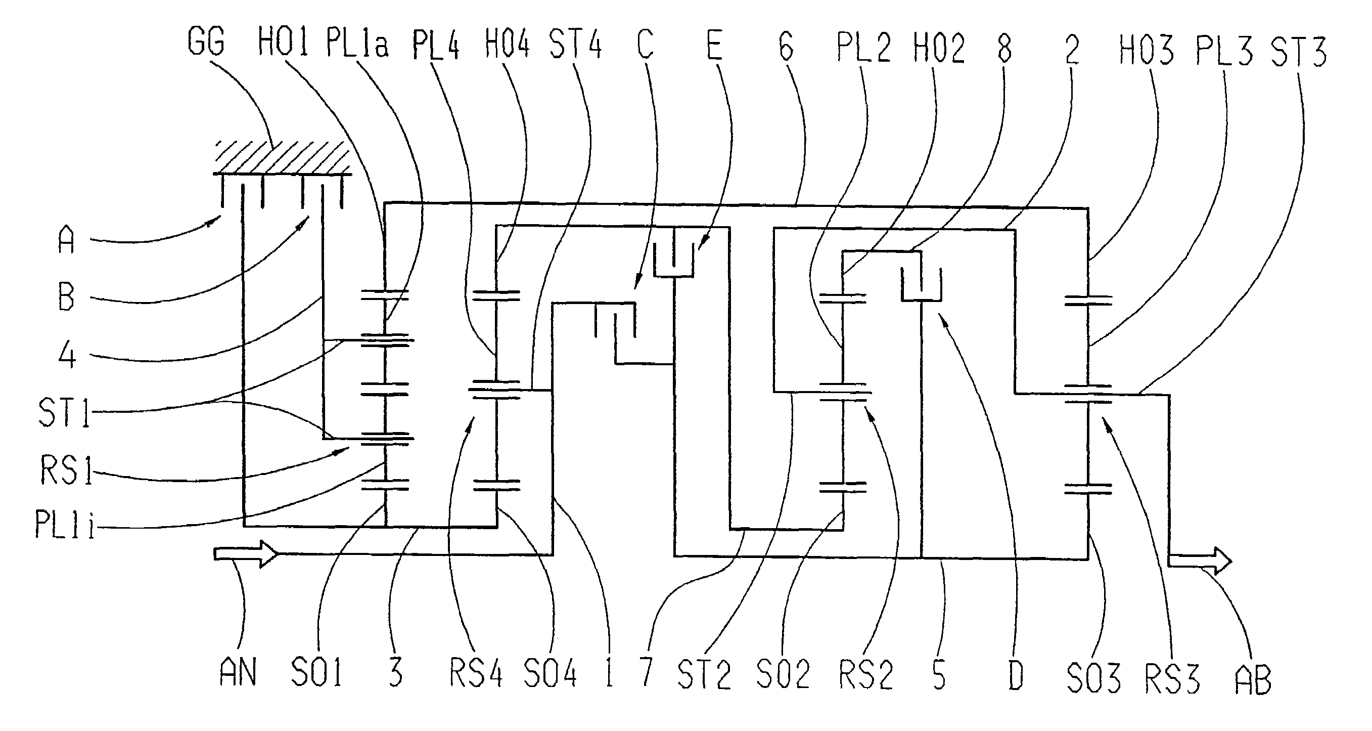
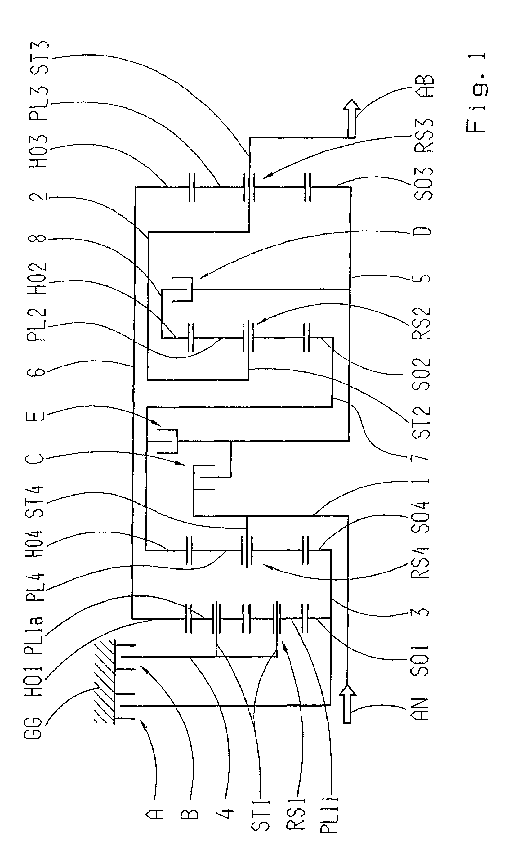
[0039]FIG. 1 shows an embodiment of an inventive multi-speed transmission in a schematic presentation. The transmission includes an input drive shaft AN and an output drive shaft AB, as well as four planetary gearsets namely RS1, RS2, RS3, RS4 and five shifting elements A, B. C. D, E, which are all contained in a transmission housing GG. The four planetary gearsets RS1, RS2, RS3, RS4 are shown, in this embodiment in the order “RS1, RS4, RS2, RS3” and are placed coaxially and successively to one another. The planetary gearsets RS2, RS3 and RS4 are designed as simple negative planetary gearsets. A negative planetary gearset possesses, as is known, planet gears, which engage the sun gear and ring gear of that planetary gearset. The ring gears of planetary gearsets RS2, RS3, RS4 are correspondingly designated with HO2, HO3 and HO4, the sun gears are shown as SO2, SO3 and SO4, while the planet gears are designated by PL2, PL3 and PL4, finally, the carriers, on which these planet gears ar...


PUM


Abstract

The multi-speed transmission having rotatable shafts, planetary gearsets (RS1, RS2, RS3, RS4) and shifting elements (A, B, C, D, E). Carrier (ST4) of gearset (RS4) and the input shaft couple as shaft (1). Carriers (ST2, ST3) of respective gearsets (RS2, RS3) and the output shaft (AB) couple as shaft (2). Sun gears (SO1, SO4) of gearsets (RS1, RS4) couple as shaft (3). Carrier (ST1) of gearset (RS1) forms shaft (4). Sun gear (SO3) forms shaft (5). Ring gears (HO1, HO3) of gearsets (RS1, RS3) couple as shaft (6). Sun and ring gears (SO2, HO4) respectively of gearsets (RS2, RS4) couple as shaft (7). Ring gear (HO2) is shaft (8). In the flow of power, elements (A, B) are respectively between shafts (3, 4) and a transmission housing; element © is between shafts (1, 5); element (D) is between shafts (5, 8); and element (E) is between shafts (5, 7).

Description

[0001]This application claims priority from German patent application serial no. 10 2006 016 192.0 filed Apr. 6, 2006.FIELD OF THE INVENTION[0002]The present invention concerns a multi-speed transmission, employing planetary gearsets, in particular, an automatic transmission for a motor vehicle, encompassing an input drive shaft, an output drive shaft, four planetary gearsets, at least eight rotatable shafts, as well as five shifting elements, the selective engagement of which determines different ratio relationships between the input drive shaft and the output drive shaft, so that eight forward gears and one reverse gear are possible.BACKGROUND OF THE INVENTION[0003]Automatic transmissions, especially for motor vehicles, include, in accord with the state of the technology, planetary gearsets, which are shifted by means of friction elements or shifting elements, such as shifting clutches and brakes and which are normally connected to a start-up element, that is subjected to slip eff...

Claims


Application Information

Patent Timeline
Patent Type & Authority Patents(United States)
IPC IPC(8): F16H3/62
CPCF16H3/666F16H2200/2043F16H2200/2012F16H2200/006
Inventor KAMM, MICHAELDIOSI, GABORHAUPT, JOSEFGUMPOLTSBERGER, GERHARDZIEMER, PETERBREHMER, MARTIN
Owner ZF FRIEDRICHSHAFEN AG
Why Eureka
Try Eureka