Balun circuit and frequency converting apparatus

a frequency conversion apparatus and balun circuit technology, applied in electrical devices, multiple-port networks, waveguide-type devices, etc., can solve the problems of undesirable differences in the signal level of an inverted side and an inverted side in the differential signal generated by the balun circuit, and difficulty in adjusting the line width in each coupling lin

Inactive Publication Date: 2009-12-15
ADVANTEST CORP
View PDF6 Cites 6 Cited by
  • Summary
  • Abstract
  • Description
  • Claims
  • Application Information

AI Technical Summary

Problems solved by technology

Furthermore, the balanced line in each coupling line is disposed parallel to the corresponding unbalanced line.
Furthermore, the levels of the signals output by the balanced lines are determined by the levels of the signals transmitted by the corresponding unbalanced lines and an amount of coupling with the unbalanced lines.
In such a case, when the coupling amount in each coupling line is set to be equal, the levels of the signals propagated to the balanced line of each coupling line are undesirably different.
In other words, the signal levels of an inverted side and a noninverted side in the differential signal generated by the balun circuit are undesirably different.
However, there are cases where it is difficult to adjust the line width in each coupling line.
For example, in a case where the balun circuit is formed on a semiconductor substrate or the like, it is difficult to dispose in a straight line a coupling line that has a line length that is one quarter of the wavelength of the transmission signal.
Therefore, with the method that adjusts the line width, the signal level of the inverted side and the noninverted side in the differential signal cannot be sufficiently adjusted.

Method used


Image

  • Balun circuit and frequency converting apparatus
  • Balun circuit and frequency converting apparatus
  • Balun circuit and frequency converting apparatus

Examples


Embodiment Construction

[0022]Hereinafter, some embodiments of the present invention will be described. The embodiments do not limit the invention according to the claims, and all the combinations of the features described in the embodiments are not necessarily essential to means provided by aspects of the invention.

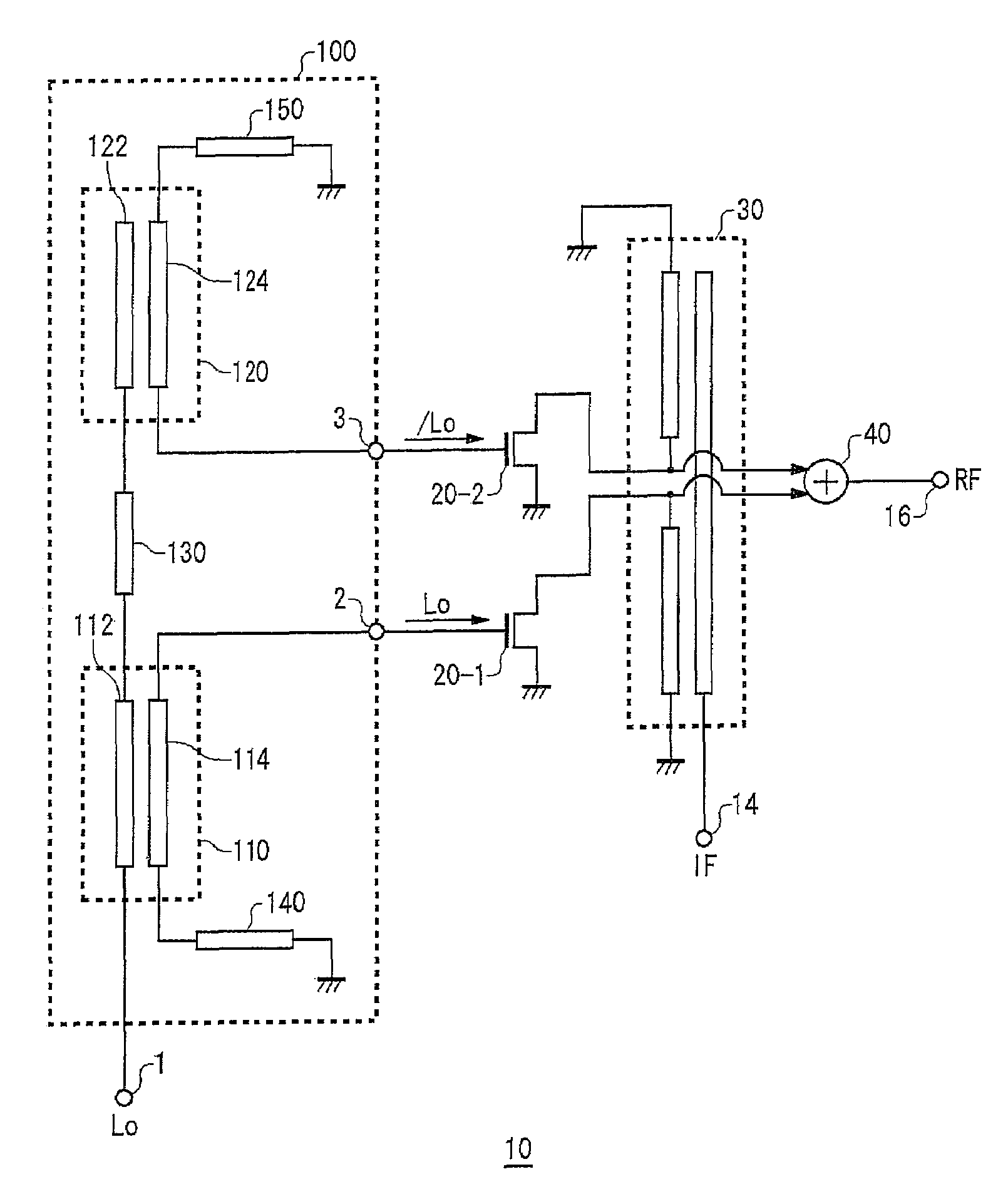
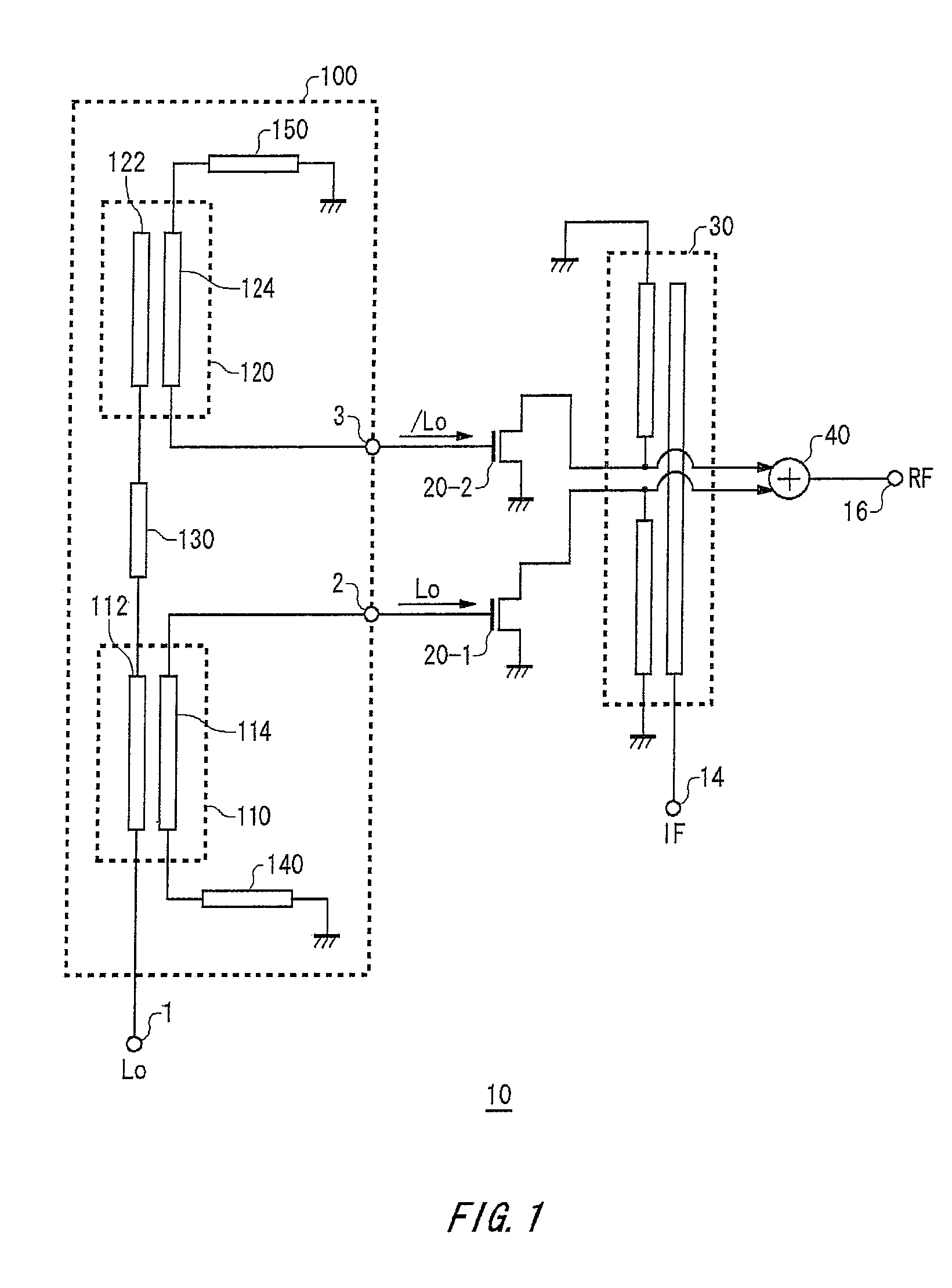
[0023]FIG. 1 shows an exemplary configuration of a frequency converting apparatus 10 according to an embodiment of the present invention. The frequency converting apparatus 10 outputs a modulated signal RF obtained by shifting a frequency of a signal to be modulated IF with a frequency of a local signal Lo. The frequency converting apparatus 10 may be formed on a semiconductor substrate, for example. The frequency converting apparatus 10 of the present embodiment is provided with a balun circuit 100, a first mixer 20-1, a second mixer 20-2, a first signal input section 30, and an output section 40.

[0024]The balun circuit 100 may function as a second signal input section that outputs a first out...


PUM


Abstract

A balun circuit is provided that includes a first coupling line in which an unbalanced line thereof is connected to a first terminal and a balanced line thereof is electrically connected to a second terminal, a second coupling line in which an unbalanced line thereof is electrically connected to the unbalanced line of the first coupling line and a balanced line thereof is electrically connected to a third terminal, a first transmission path that is serially connected between the balanced line of the first coupling line and a ground potential, a second transmission path that is serially connected between the balanced line of the second coupling line and a ground potential, and a third transmission path that is serially connected between the unbalanced line of the first coupling line and the unbalanced line of the second coupling line. These transmission lines are formed such that an amplitude characteristic of S12 is the same as an amplitude characteristic of S13 and a phase characteristic of S12 is inverted in relation to a phase characteristic of S13.

Description

BACKGROUND[0001]1. Technical Field[0002]The present invention relates to a balun circuit and a frequency converting apparatus and, more particularly, the present invention relates to a balun circuit disposed between a first terminal, a second terminal, and a third terminal and a frequency converting apparatus that outputs a modulated signal obtained by shifting a frequency of a signal to be modulated according to a frequency of a local signal.[0003]2. Related Art[0004]A balun circuit is conventionally known as a circuit that generates a differential signal. For example, the balun circuit generates the differential signal through a signal output by two coupling lines connected in a cascading manner as in, for example, Japanese Patent Application Publication No. 2002-232215 (Patent Document 1).[0005]Each coupling line includes an unbalanced line and a balanced line. The unbalanced line in each coupling line is disposed as a single continuous line. Furthermore, the balanced line in eac...

Claims


Application Information

Patent Timeline
Patent Type & Authority Patents(United States)
IPC IPC(8): H03H7/42H01P5/04
CPCH01P5/10
Inventor OKABE, HIDEYUKI
Owner ADVANTEST CORP
Why Eureka
Try Eureka