Object detection portal with video display overlay

Inactive Publication Date: 2009-12-15
QUANTUM MAGNETICS
View PDF24 Cites 20 Cited by
  • Summary
  • Abstract
  • Description
  • Claims
  • Application Information

AI Technical Summary

Benefits of technology

[0010]A real time video image of target location provides the following significant operational advantages over threat location systems which provide “after the fact” object location information. Significant human factors issues inherent in manual second level search procedures resulting from operator training, motivation, experience, fatigue, boredom or complacency are mitigated by providing real time object viewing. Importantly, the need for frequent “red-team” effectiveness testing to ensure

Problems solved by technology

Such systems are notoriously imprecise in distinguishing between benign objects and dangerous objects.
The result of a false indication is that screening personnel need

Method used


Image

  • Object detection portal with video display overlay
  • Object detection portal with video display overlay
  • Object detection portal with video display overlay

Examples


Embodiment Construction

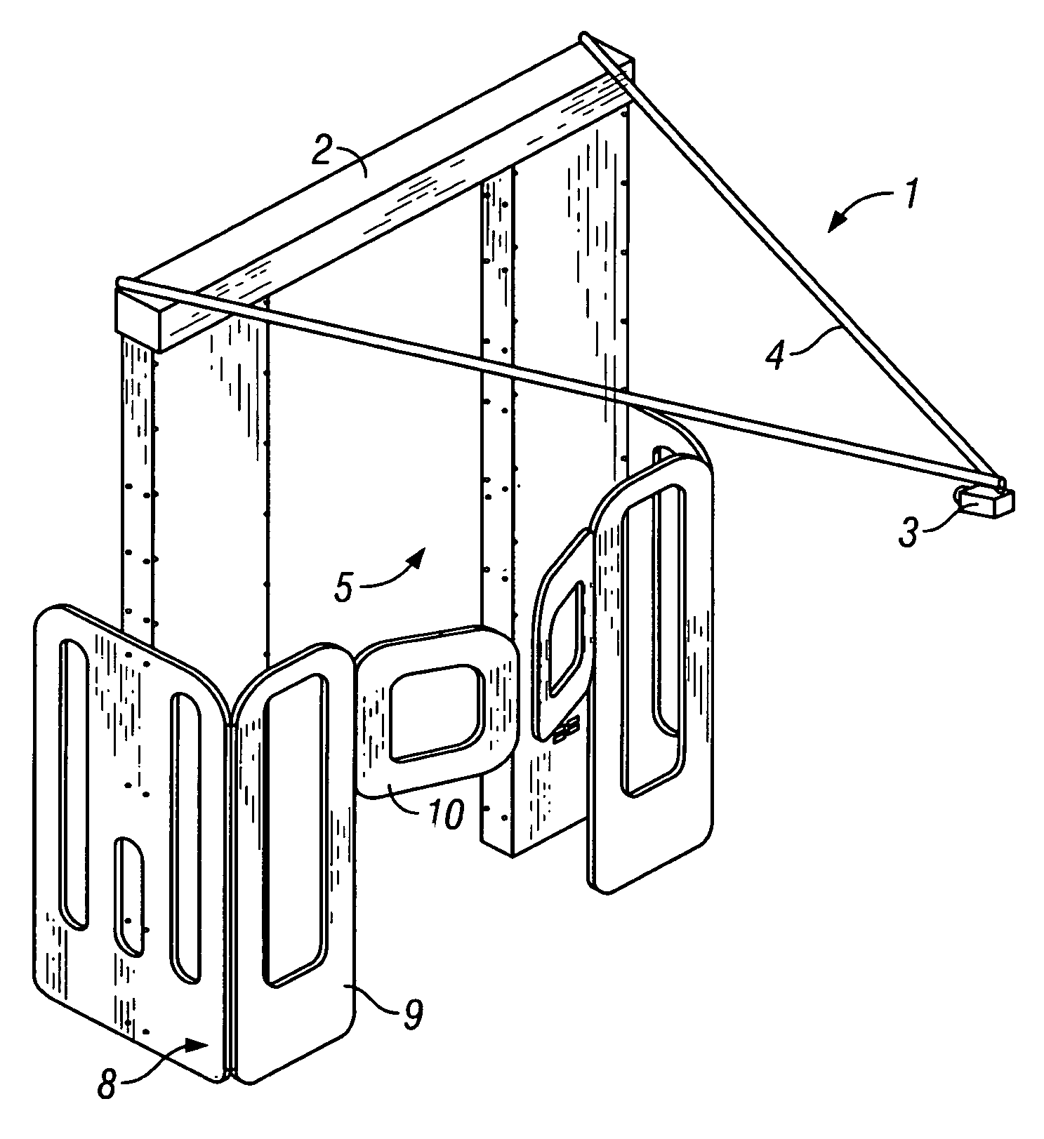
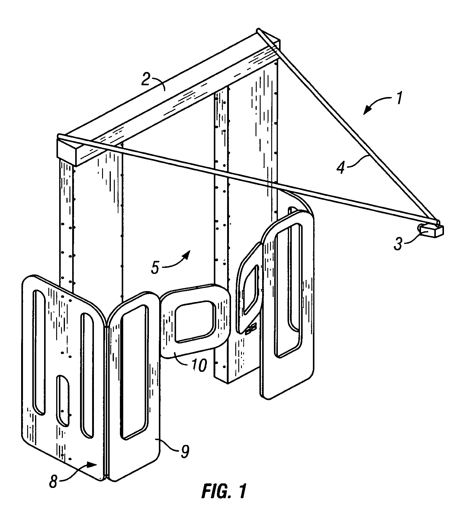
[0024]With reference now to the drawings, FIG. 1 is an axonometric view elevation of object detection portal 2 in apparatus 1 constructed in accordance with an embodiment of the present invention. Video camera 3 is mounted on support 4 in order to provide a display of scanned volume 5 in which a subject 14 (FIG. 2) to be scanned will be positioned. Subject 14 to be scanned will often be a person such as an airline passenger. Exit assembly 8 is preferably provided to impede the progress of a scan subject until the absence of a threat is confirmed. The exit assembly comprises barrier 9 closed by automatically operated gate 10. More than one video camera 3, each in a different position, may be used at a portal. This can assist in rapid resolution of threat objects.

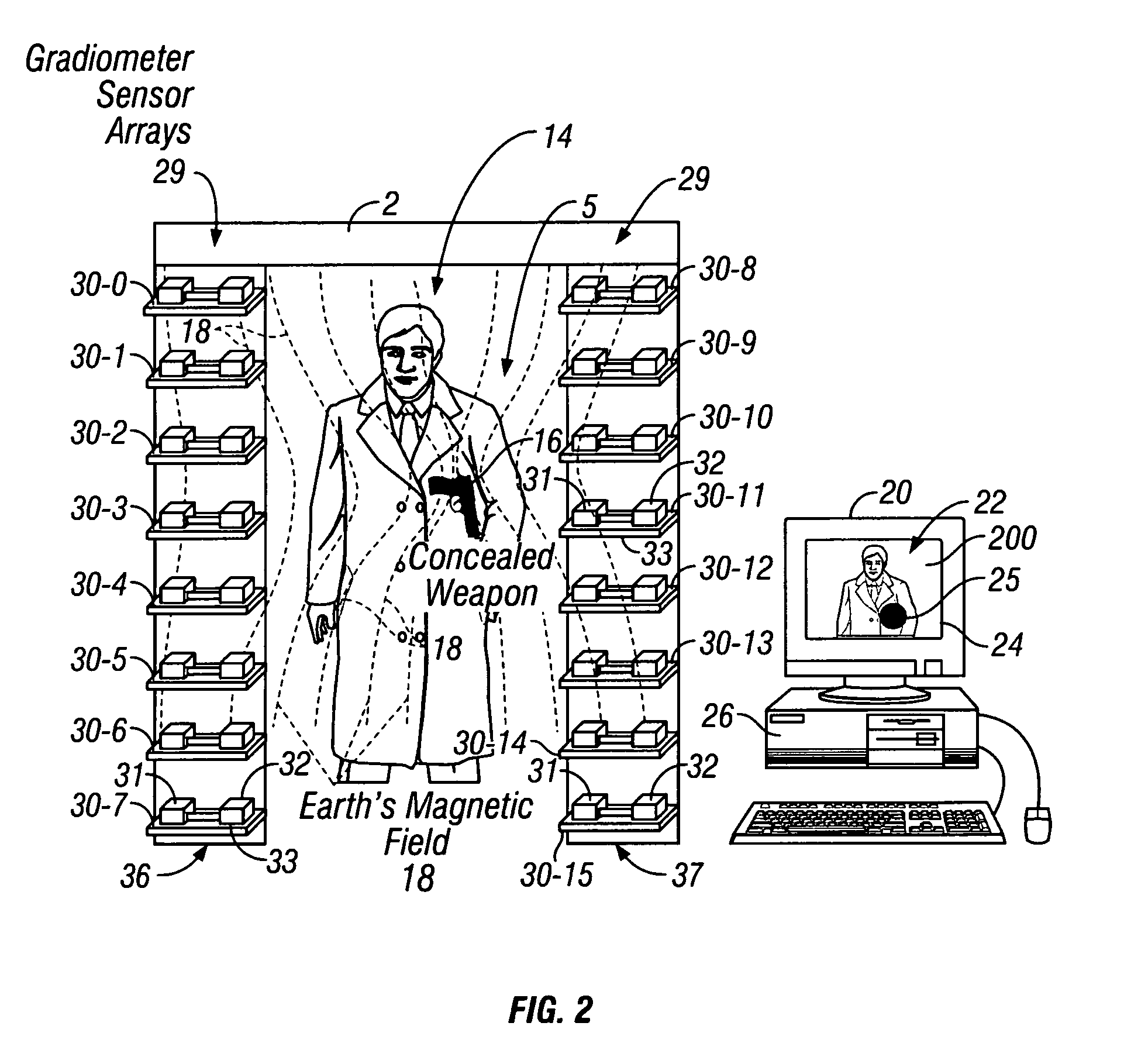
[0025]FIG. 2 is an elevation in schematic form of portal 2 and scan subject 14 carrying a threat object 16. The threat object 16 will cause perturbation in the sensing of flux lines in the Earth's magnetic field as indicated ...


PUM


Abstract

An object detection portal wherein a video image is obtained of a volume or area being scanned, and location of a threat object is determined and displayed in real time as an indicator overlay on the video image. An individual subject being scanned may be continuously monitored by an operator during an object divesting process, and an operator may view the threat object moving from or remaining with the subject. Object location information is supplied to a video driver to superimpose the overlay on a real time image of a subject. The scanning portal may interact with an exit barrier. The exit barrier may be activated automatically in response to sensing of a threat.

Description

BACKGROUND[0001]1. Field of the Invention[0002]The present invention relates to object detection portals and more specifically to a system in which locations of detected objects are displayed as an indicator overlay on a video image of the volume being scanned.[0003]2. Discussion of Related Art[0004]A very common form of object detection portal is a metal detector archway such as a weapons detector portal used for security screening. Metal detection portals typically operate on the principles of inductive and / or magnetic detection of conductive or ferromagnetic objects such as guns or knives. Typically a person to be inspected walks through an archway structure containing an array of inductive coils and any resultant perturbation of the inductive coil fields is determined. Normally this perturbation is quantified by portal electronics to produce a signal whose magnitude is compared to a preset threshold value. If the signal is equal to or greater than the threshold value the portal ...

Claims


Application Information

Patent Timeline
IPC IPC(8): H04N7/18G01V3/10G01V11/00
CPCG01V11/00G01V3/104
Inventor BEEVOR, SIMON PETERPERRY, ALEXANDER R.HANLEY, GERARD ANDREWWOLFF, STEVECZIPOTT, PETER V.
Owner QUANTUM MAGNETICS
Why Eureka
Try Eureka