Electronic apparatus

a technology of electronic equipment and parts, applied in the field of electronic equipment, can solve the problems of not being cooled efficiently, affecting the appearance of the outside, and affecting the efficiency of cooling, so as to improve cooling efficiency, reduce the number of parts, and reduce the size

Inactive Publication Date: 2009-12-15
FUJITSU CLIENT COMPUTING LTD
View PDF44 Cites 35 Cited by
  • Summary
  • Abstract
  • Description
  • Claims
  • Application Information

AI Technical Summary

Benefits of technology

[0017]The present invention has been made with a view toward solving the above problems. It is a technical object of the present invention to provide an electronic apparatus capable of cooling a plurality of heat generating devices by a single cooling fan, thereby making it possible to achieve a reduction in the number of parts, a reduction in size, and an improvement in cooling efficiency, and to suppress noise generation.
[0020]According to the present invention, a plurality of heat generating devices are arranged in parallel in a direction crossing the central axis of the impeller of the cooling device, so the airflow from the cooling device directly hits the plurality of heat generating devices. Thus, a plurality of heat generating devices can be cooled by a single cooling device, thereby making it possible to achieve a reduction in the number of parts, an improvement in cooling efficiency, and a reduction in size, and to suppress noise generation.
[0023](4) Examples of the heat generating devices further comprise a LCD (liquid crystal display). In a computer integrated with an LCD, it is possible to cool the power source unit, the CPU, the disk drive device, and the LCD by a single cooling device.
[0033]According to the present invention, it is possible to cool a plurality of heat generating devices by a single cooling device, thereby making it possible to achieve a reduction in the number of parts, an improvement in cooling efficiency, and a reduction in size, and to suppress noise generation.

Problems solved by technology

As a result, the airflows are changed in direction, or reduced in pressure, so there is a fear of the heat generating devices 51 through 56 not being cooled efficiently.
Further, when large cooling fans are installed, the portions where such large cooling fans are installed protrude from the remaining portion of the apparatus, resulting in a rather unbalanced outward appearance.

Method used


Image

  • Electronic apparatus
  • Electronic apparatus
  • Electronic apparatus

Examples


Embodiment Construction

[0040]In the following, an electronic apparatus according to an embodiment of the present invention will be described with reference to the drawings.

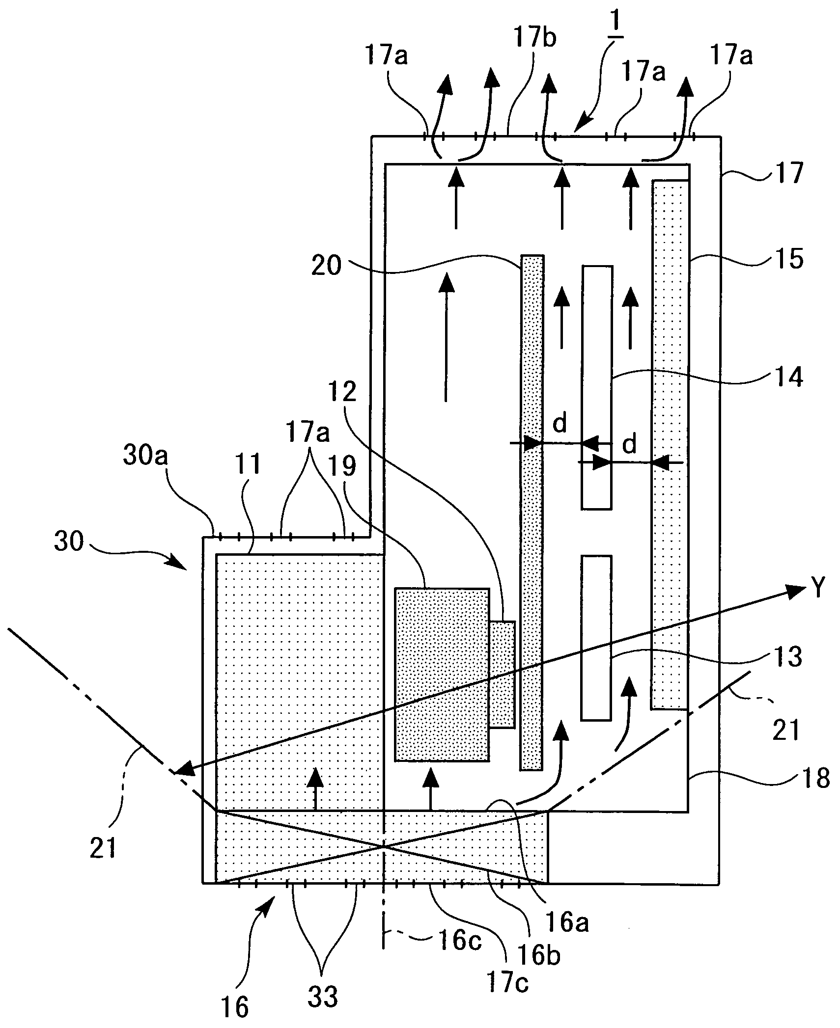
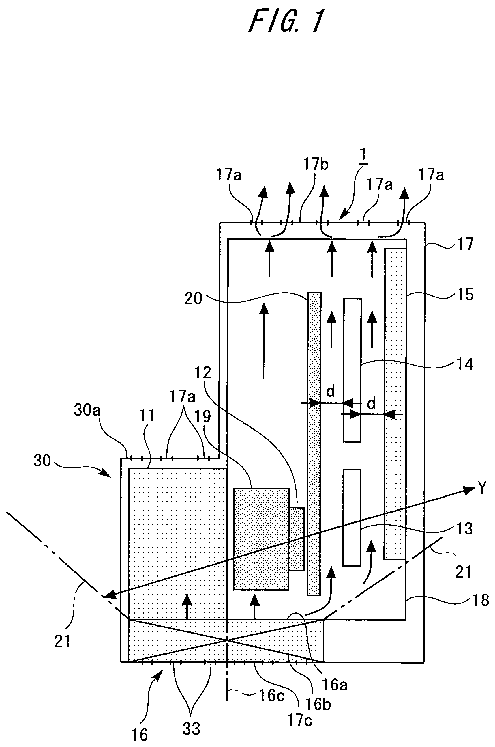
[0041]FIG. 1 shows a personal computer 1, which is an electronic apparatus according to this embodiment. The personal computer 1 is equipped with heat generating devices: a power source unit 11; a CPU 12; an FD (flexible disk) drive device 13; a CD (compact disc) / DVD (digital video disk) drive device 14; and an LCD (liquid crystal display) 15; and a cooling fan 16, which is a single cooling device for cooling the above heat generating devices.

[0042]In FIG. 1, reference numeral 17 indicates a casing, reference numeral 18 indicates a frame for mounting the above-mentioned heat generating devices 11 through 15, reference numeral 19 indicates a heat sink for cooling the CPU 12, and reference numeral 20 indicates a main substrate. The personal computer 1 is further equipped with general devices (not shown) other than those mentioned above.

[...


PUM


Abstract

A personal computer (electronic apparatus) (1) is equipped with a plurality of heat generating devices: a power source unit (11), a CPU (12), an FD drive device (13), a CD / DVD drive device (14), and an LCD (15), and a cooling fan (16) for cooling the plurality of heat generating devices (11) through (15). The plurality of heat generating devices (11) through (15) are arranged in parallel in a direction Y which crosses a central axis (16c) of an impeller (16b) of the cooling fan (16). Further, the heat generating devices (11) through (15) are arranged within a blowing range (21) of the cooling fan (16).

Description

BACKGROUND OF THE INVENTION[0001]1. Field of the Invention[0002]The present invention relates to an electronic apparatus, such as a computer, which has a plurality of heat generating devices.[0003]2. Description of the Related Technology[0004]A personal computer is generally equipped with a power source unit, a CPU (central processing unit), an FD (flexible disk) drive device, and a CD (compact disc) drive device. Some personal computers are integrally provided with an LCD (liquid crystal display).[0005]The power source unit, the CPU, the drive devices, and the LCD generate a relatively large amount of heat. In particular, the power source unit and the CPU generate a large amount of heat. The CPU is vulnerable to heat, so that it is necessary to cool the CPU and the heat generating devices around it.[0006]As shown in FIG. 6, in a conventional personal computer 50, it is common practice to cool a CPU 51 by a heat sink 52 and, at the same time, to cool heat generating devices, such as...

Claims


Application Information

Patent Timeline
Patent Type & Authority Patents(United States)
IPC IPC(8): H05K7/20
CPCH05K7/20972G06F1/20
Inventor SHINOTOU, KOUICHIFUJIKAWA, HIDEYUKI
Owner FUJITSU CLIENT COMPUTING LTD
Why Eureka
Try Eureka