
Distributed debugger environment

a debugger environment and distributed technology, applied in the field of distributed debugger environment, can solve the problems of not knowing which of the plurality of machines is running the portion of the program, and the developer might not even know that the machine he wants to break exists

Active Publication Date: 2009-12-15
MICROSOFT TECH LICENSING LLC
View PDF9 Cites 24 Cited by
  • Summary
  • Abstract
  • Description
  • Claims
  • Application Information

AI Technical Summary

Benefits of technology

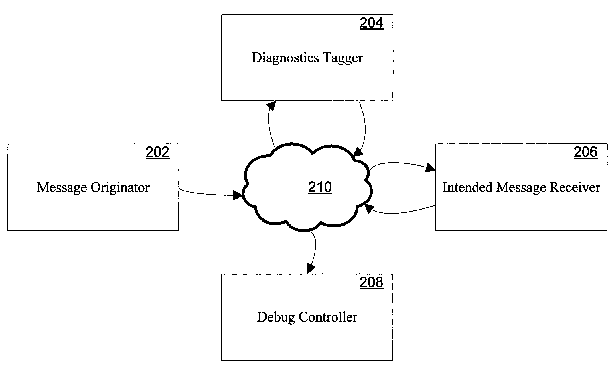
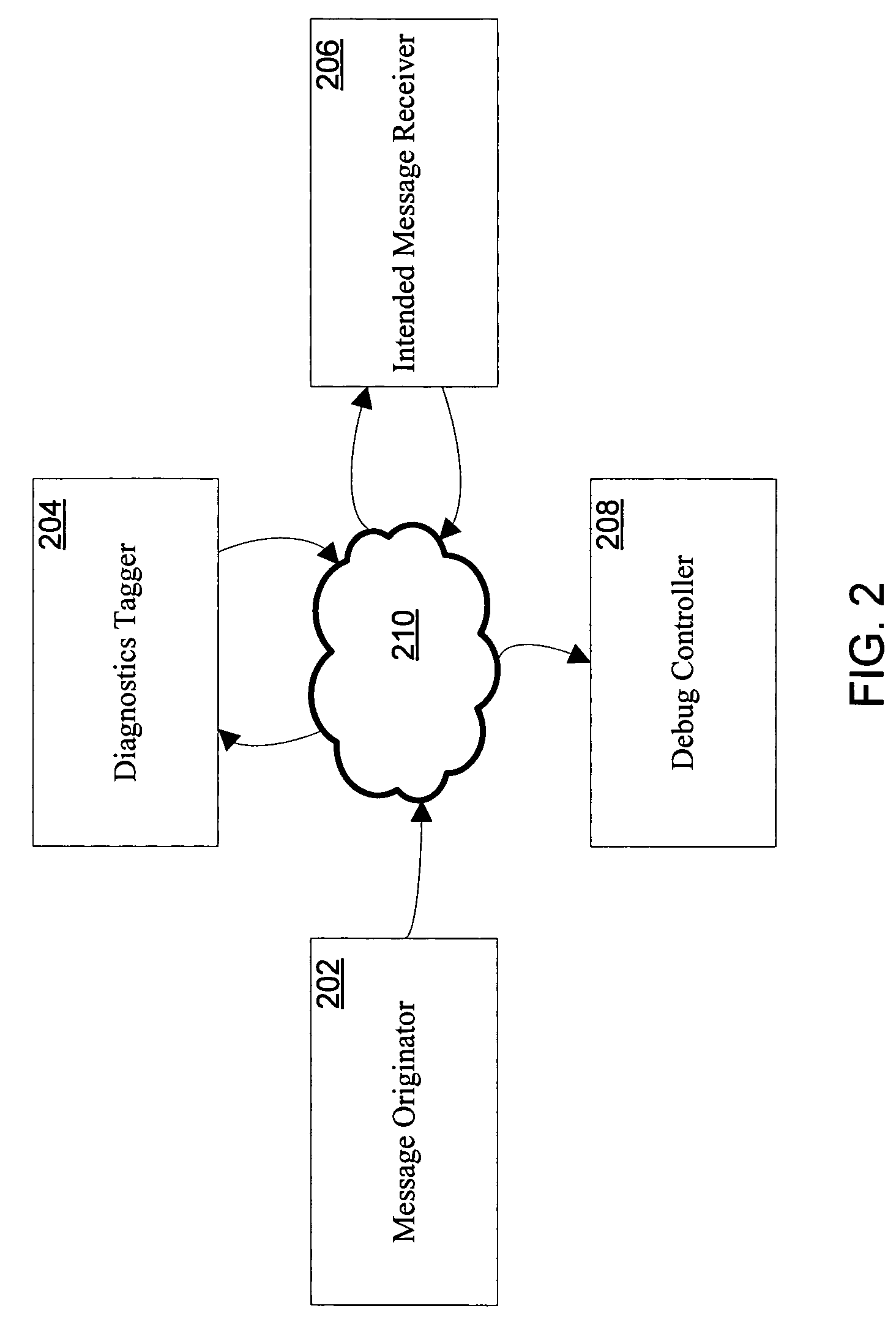
The invention provides a system and method for debugging software web services in an asynchronous environment. The system includes a message originator, a diagnostics tagger, an intended message receiver, and a debug controller. The components communicate with each other through SOAP messages. The diagnostics tagger modifies the SOAP message to include certain elements that cause a breakpoint to be triggered. The intended message receiver receives the message and calls back to the debug controller when a breakpoint is detected. The system allows for distributed debugging and improves efficiency and accuracy in identifying and resolving issues in software web services.

Problems solved by technology

Sometimes, however, the developer does not know which of the plurality of machines is running the portion of the program he wants to break.
The developer might not even know that the machine he wants to break exists.

Method used


Image

  • Distributed debugger environment
  • Distributed debugger environment
  • Distributed debugger environment

Examples


Embodiment Construction

Exemplary Computing Environment

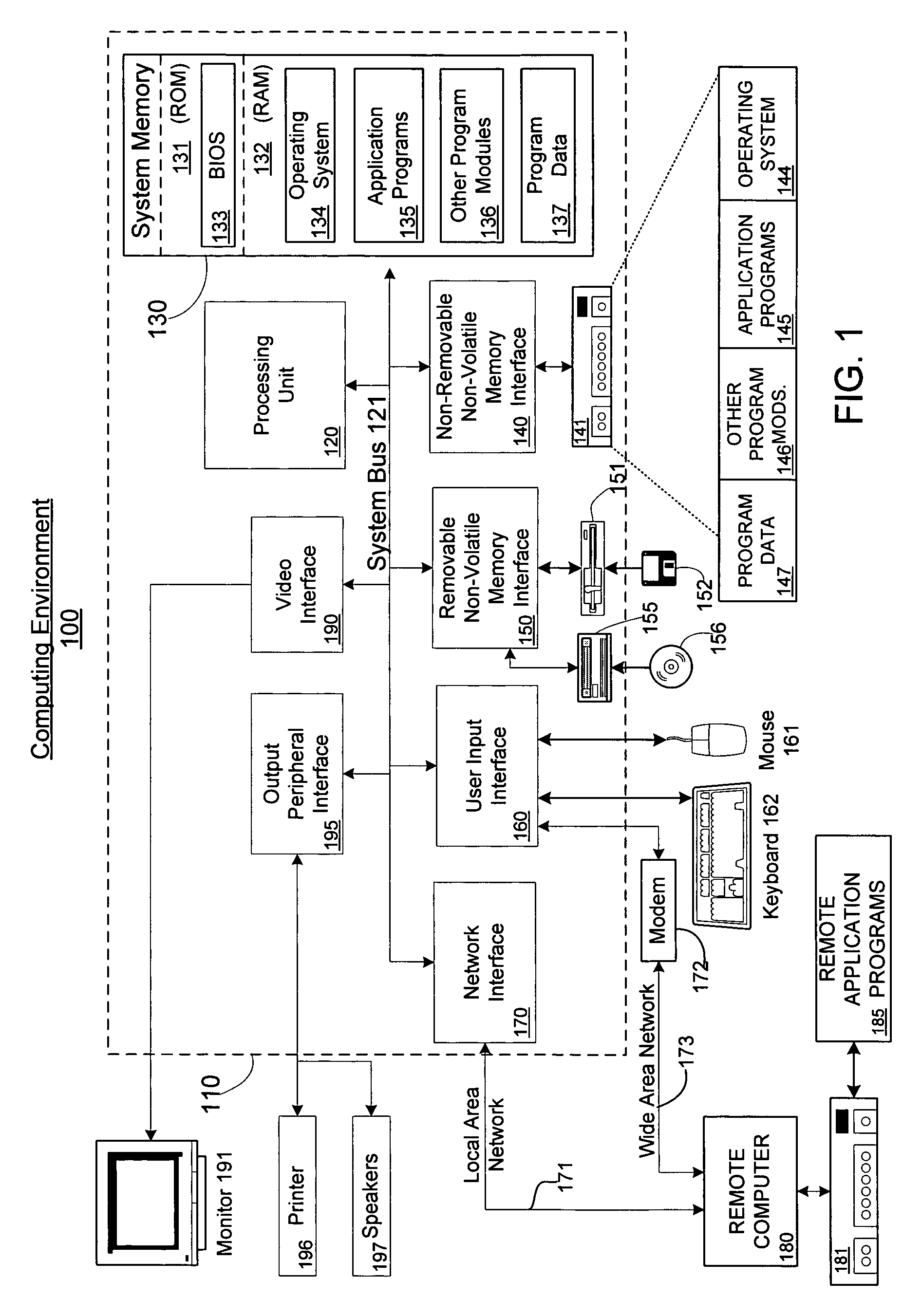
[0015]FIG. 1 illustrates an example of a suitable computing system environment 100 in which the invention may be implemented. The computing system environment 100 is only one example of a suitable computing environment and is not intended to suggest any limitation as to the scope of use or functionality of the invention. Neither should the computing environment 100 be interpreted as having any dependency or requirement relating to any one or combination of components illustrated in the exemplary operating environment 100.

[0016]The invention is operational with numerous other general purpose or special purpose computing system environments or configurations. Examples of well known computing systems, environments, and / or configurations that may be suitable for use with the invention include, but are not limited to, personal computers, server computers, hand-held or laptop devices, multiprocessor systems, microprocessor-based systems, set top boxes, progr...


PUM


Abstract

Systems and methods for providing distributed debugging in an extensible SOAP environment of asynchronous software web services are disclosed. Such a system may include a message originator, a diagnostics tagger, an intended message receiver, and a debug controller, which may communicate with one another via SOAP messages. The message originator originally puts the SOAP message onto the network. The diagnostics tagger modifies the SOAP message to include certain diagnostics elements that cause a breakpoint to be triggered. The intended message receiver eventually receives the message and is expected to trigger the breakpoint. The debug controller is a process that is called by the intended message receiver when a breakpoint is detected. The header of the SOAP message may include a security element and a diagnostics element. The diagnostics element may include one or more breakpoint elements. Each breakpoint element may include a debugging controller element, and one or more condition elements. Each condition element may include a logical expression. The intended message receiver determines whether the conditions are met. If the conditions are met, then the breakpoint is triggered.

Description

FIELD OF THE INVENTION[0001]Generally, the invention relates to computer program debuggers. More particularly, the invention relates to systems and methods for providing distributed debugging in an extensible SOAP environment of asynchronous software web services.BACKGROUND OF THE INVENTION[0002]In the past, computer programs could be considered a stack of instructions executed sequentially on a single machine. The developer, typically using a debugger running on the same machine, could set a breakpoint at some point in the stack. When the breakpoint is encountered, the program stops running. The developer could then glean whatever information might be of interest.[0003]Nowadays, computer programs often run in a “distributed” environment, where programs run across a plurality (tens, sometimes hundreds) of networked machines. Processes distributed among the several machines communicate with each other over the network via simple object access protocol (“SOAP”) messages. Consequently,...

Claims


Application Information

Patent Timeline
Patent Type & Authority Patents(United States)
IPC IPC(8): G06F9/44
CPCG06F9/4843G06F11/3664G06F11/362G06F9/546
Inventor CALSYN, MARTIN R.CHRYSANTHAKOPOULOS, GEORGIOSZISSIMOPOULOS, VASILEIOS
Owner MICROSOFT TECH LICENSING LLC
Learn More