Cross panel

a technology of suspended ceilings and cross panels, which is applied in the direction of walls, constructions, building components, etc., can solve the problems of prohibitively expensive, difficult for a single trade to complete a ceiling grid installation without, and high cost of customizing the cross tees

Active Publication Date: 2009-12-22
USG INTERIORS INC
View PDF13 Cites 15 Cited by
  • Summary
  • Abstract
  • Description
  • Claims
  • Application Information

AI Technical Summary

Benefits of technology

[0005]The panel can be arranged to work with and / or without the module dimensions of the grid. Besides affording a broad range of rectangular shapes and sizes, the panel can be arranged with a variety of surface treatments including textures, contours extending above and / or below the plane of the surrounding grid, and small and large perforations of any desired pattern or spacing. Among other advantages, the panel can have punching for sprinkler heads, can conceal public address speakers, and can act as a return air grille for HVAC systems, thus further organizing the ceiling plane in an aesthetic way while providing these utilities or functions.

Problems solved by technology

This customization of the cross tees can be expensive, if not prohibitively expensive.
Even when customized cross tees can be economically justified, there remains the problem of fashioning a ceiling tile or panel to an appropriate custom size.
With traditional grid and panel systems, it can be difficult for a single trade to complete a ceiling grid installation without interruption due to the overlapping of tasks of different trades.
For example, the ceiling installation can involve issues of the division of labor between carpenters and sheet metal workers, for example.

Method used


Image

  • Cross panel
  • Cross panel
  • Cross panel

Examples


Embodiment Construction

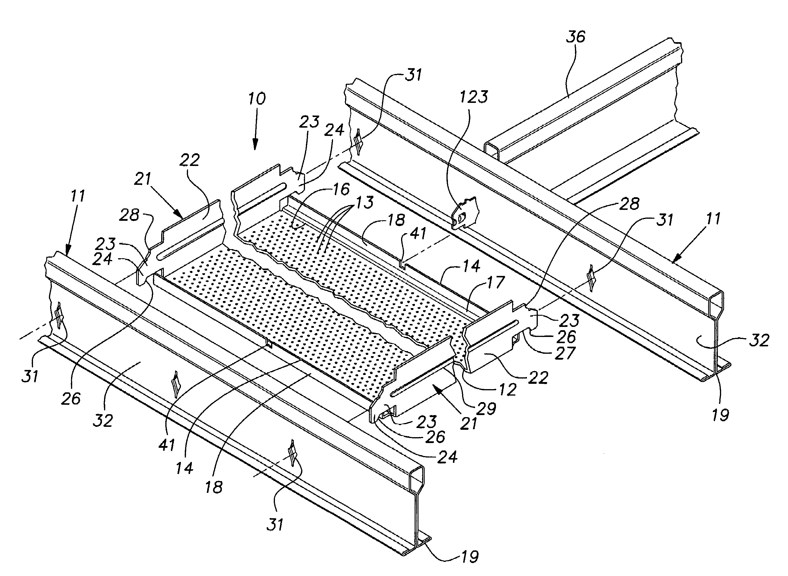
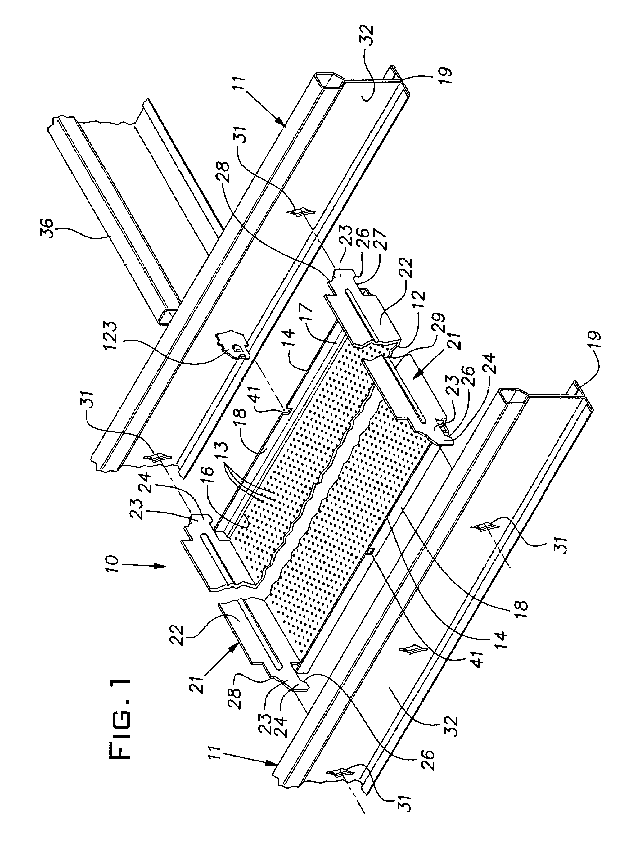
[0011]FIG. 1 shows a ceiling cross panel 10 in a fragmentary exploded perspective assembly view with a pair of parallel main tees 11. The illustrated cross panel 10 is formed of a single sheet of light gauge sheet metal such as aluminum or mild steel. In the illustrated example, the cross panel has a face 12 visible from below the ceiling and having a rectangular periphery. The face, in the illustrated case, is perforated with a multitude of small regularly spaced holes throughout substantially its full area. The holes or perforations 13 can serve to pass sound and / or permit air circulation through the cross panel 10. The panel face 12, at least, can be painted or otherwise finished as desired.

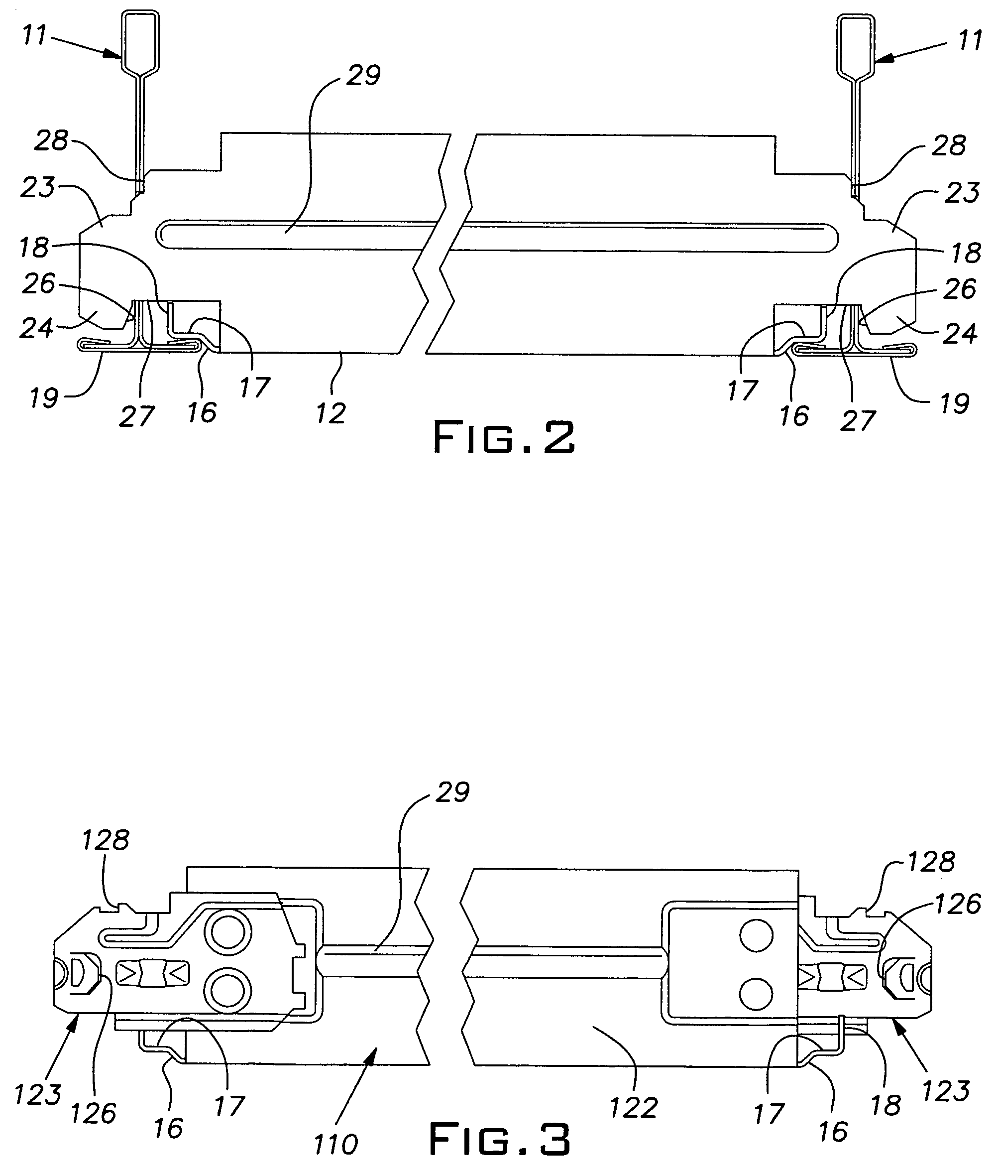
[0012]Opposed edges 14 of the cross panel, sometimes referred to hereinafter as longitudinal edges, are parallel with the longitudinal direction of the main tees 11. The longitudinal edges 14 each have an associated small upward step 16 (FIG. 2), a relatively narrow horizontal shelf 17, and a ...


PUM


Abstract

A cross panel for a grid type suspended ceiling comprising a sheet metal body forming a rectangular face adapted to close the space between the flanges of a pair of parallel grid tees. The panel has four connectors each adjacent a respective corner of the panel face and adapted to extend through a slot in the web of the adjacent grid tee for interlocking the panel to the tees in a manner that maintains the parallel spacing and alignment of the tees and affords a simple, aesthetically pleasing appearance.

Description

BACKGROUND OF THE INVENTION[0001]The invention relates to suspended ceiling systems and, in particular, to specialized panels for such systems.PRIOR ART[0002]In contemporary commercial buildings, grid type suspended ceilings are widely, if not almost universally, used. In most suspended ceilings, the ceiling grid pattern is interrupted by light fixtures and, often, conditioning air vents, sprinkler heads, speakers, utility conduits, exit signs, and so forth. Architects strive to integrate these necessary service related elements into the grid to achieve a simple and, therefore, more aesthetically pleasing appearance.[0003]Frequently, elongated light fixtures and / or air vents are longitudinally aligned and spaced along a line that interrupts the regular rectangular grid pattern, ordinarily being parallel to one or the other directions of the grid. Where these fixtures are of a size, typically a width, different from a standard grid module dimension, it has been a practice to custom m...

Claims


Application Information

Patent Timeline
Patent Type & Authority Patents(United States)
IPC IPC(8): E04B9/00
CPCE04B9/241E04B9/122
Inventor AHREN, GREGORY M.BANKSTON, JOHN D.
Owner USG INTERIORS INC
Why Eureka
Try Eureka