Forwardly-placed firearm fire control assembly

a forward-placed, firearm technology, applied in the field of firearms, can solve the problems of wasting a great deal of time, and a very cumbersome and awkward weapon system of the rifl

Inactive Publication Date: 2009-12-22
BATTELLE ENERGY ALLIANCE LLC
View PDF48 Cites 60 Cited by
  • Summary
  • Abstract
  • Description
  • Claims
  • Application Information

AI Technical Summary

Benefits of technology

[0010]A firearm fire control assembly is adapted to be disposed in a forwardly placed, support-hand operative relationship within a firearm. The firearm has, in operative connected relationship one with another, a barrel and a receiver in a forward assembly, either or both of which is connected to a forestock. The firearm also has, in operative disposition therewithin, the following firing mechanisms: a combination of a firing pin and a firearm hammer adapted to engage and fire a cartridge within the firearm, a sear assembly to alternately engage and disengage the combination of the firearm hammer and firing pin, and a trigger assembly including a movable trigger mechanism that is operable to engage the sear assembly

Problems solved by technology

However, this extended, usually rearward length in these prior firearms also represents length and corresponding internal area/volume used only during the loading and unloading processes, and is otherwise substantially unused, relatively empty space during any other period.
In many firearm situations, this empty space has not provided any hindrance in operation or effect.
Either way, repositioning or switching weapons wastes a great deal of time in breaching situations and the loss of precious seconds could result in undesirable consequences.
Moreover, the connection of an otherwise conventional shotgun onto a parent weapon such as a rifle provides a very cumbersome and awkward weapon system.
Moreover, such an over/under or underslung connection of a rifle and conve

Method used


Image

  • Forwardly-placed firearm fire control assembly
  • Forwardly-placed firearm fire control assembly
  • Forwardly-placed firearm fire control assembly

Examples


Embodiment Construction

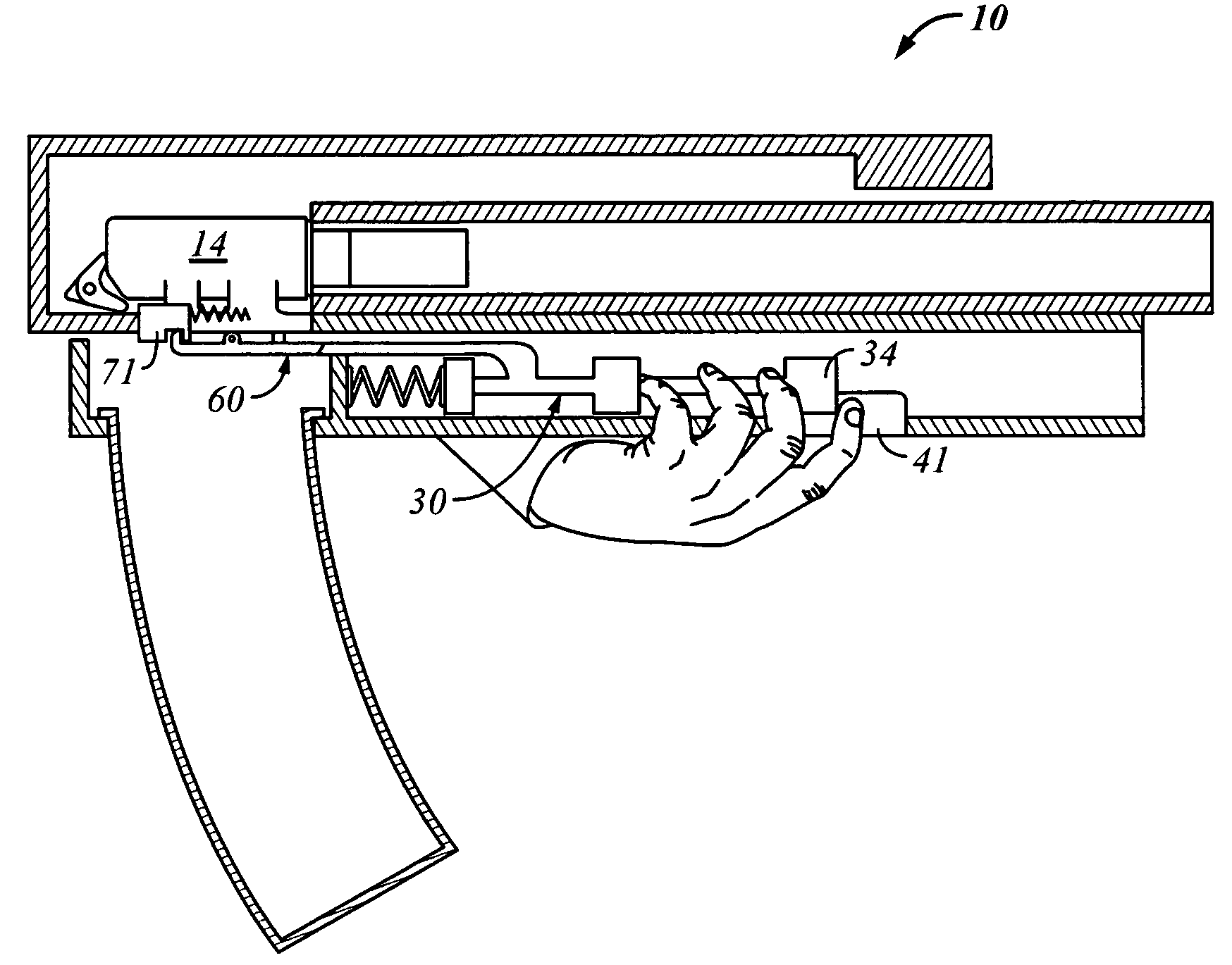
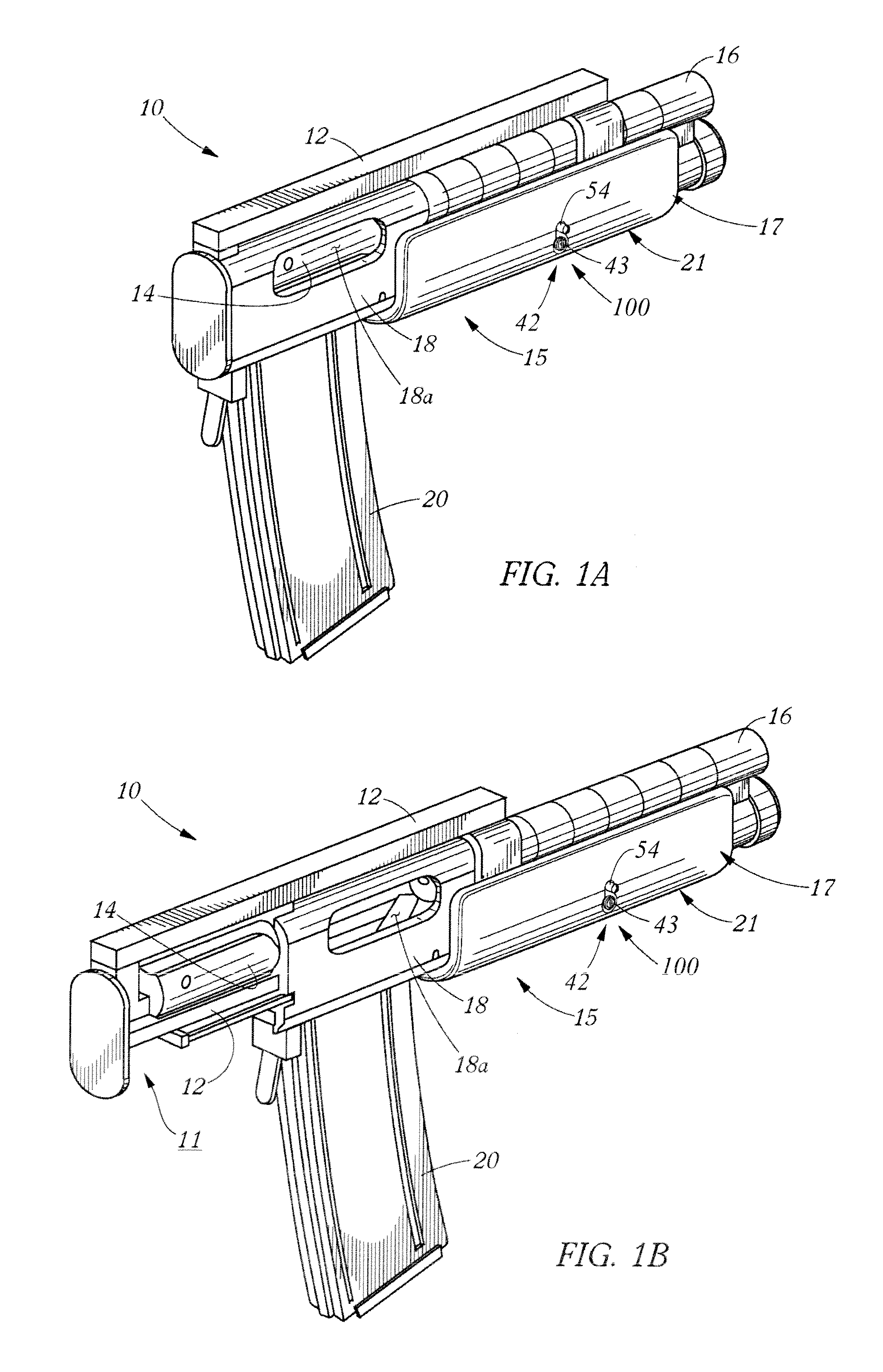
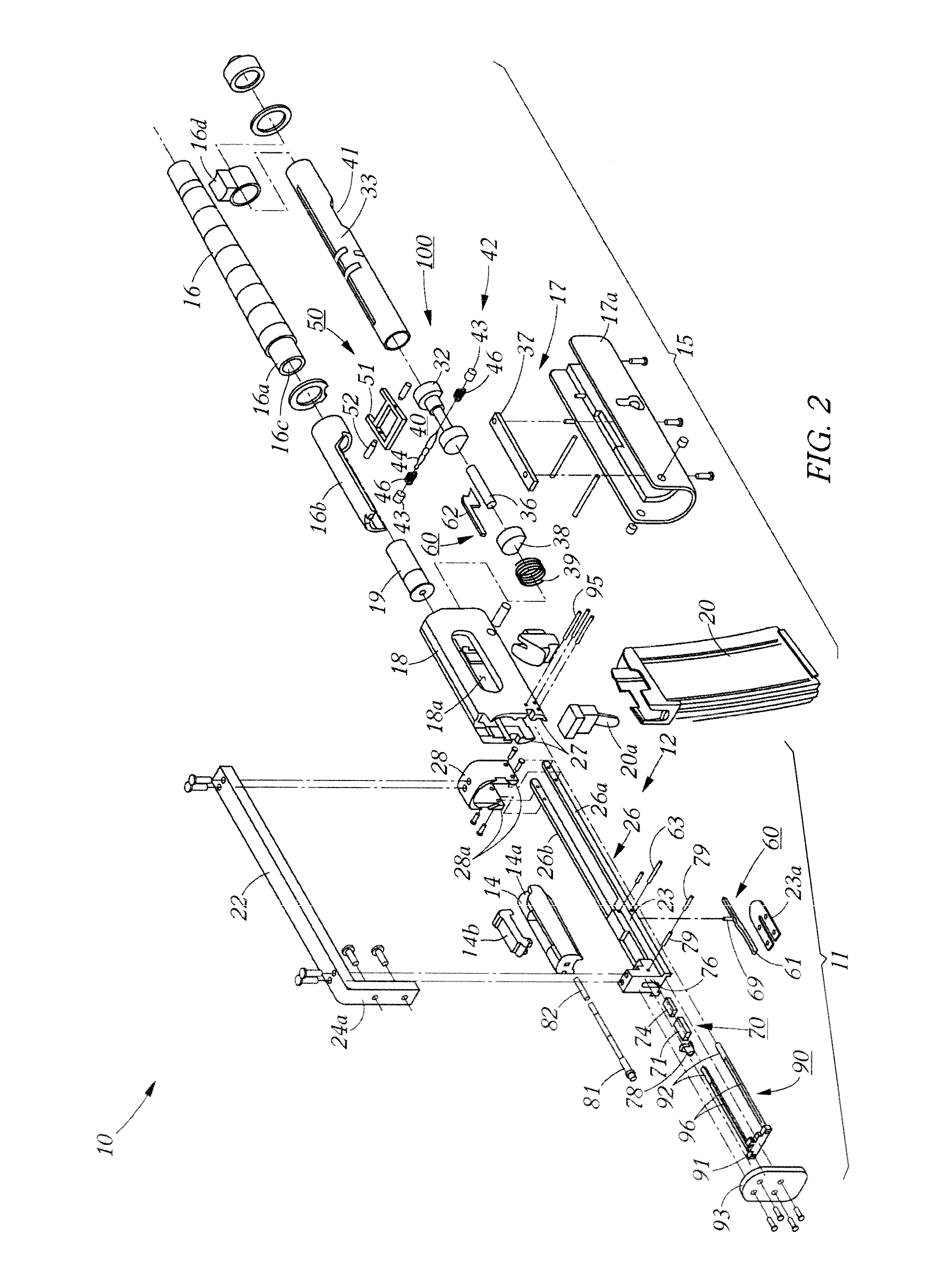
[0036]Disclosed herein are compact weapons usable alone and / or as secondary weapons integrated with an operator's primary weapon. More particularly, the weapons herein described are typically shoulder-fired and / or two-handed firearms, having their respective receivers reduced in size, especially in length, to reduce the overall length of each firearm. This may be achieved in part by making the bolt or other breech closure or blocking surface or device of each such firearm relatively stationary and making the corresponding barrel forwardly movable relative thereto for loading and unloading. Also described herein are embodiments where the receiver, magazine and barrel of a firearm are joined together and all of these components being movable with / as the loading and unloading pump apparatus. Also described herein are alternative parts of the movable pump elements being movable to a forward position on the firearm. In some embodiments, the trigger and / or other fire controls, such as the...


PUM


Abstract

A firearm fire control assembly for disposition in a forwardly placed support-hand operative relationship within a firearm having a combination of a firing pin and a firearm hammer adapted to engage and fire a cartridge, a sear assembly to alternately engage and disengage the combination of the firearm hammer and firing pin, and a trigger assembly including a movable trigger mechanism that is operable to engage the sear assembly to cause the firearm hammer firing pin combination to fire the firearm, a fire control assembly including a fire control depression member and a fire control rod operably connected to the depression member, and being positioned in a forward disposition disposed within a forestock of the firearm, and the depression member adapted to be operably engaged and depressed by the user's conventional forwardly placed support hand to maneuver the fire control rod to provide firing control of the firing of the firearm.

Description

GOVERNMENT RIGHTS[0001]This invention was made with Government support under Contract No. DE-AC07-99ID13727 awarded by the U.S. Department of Energy. The Government has certain rights in the invention.CROSS-REFERENCE TO RELATED APPLICATIONS[0002]This application is related to U.S. application Ser. No. 10 / 937,221, filed Sep. 8, 2004, entitled “SEPARATING FIREARM SEAR,” pending, U.S. application Ser. No. 10 / 939,016, filed Sep. 9, 2004, entitled “FIREARM TRIGGER ASSEMBLY,” pending, U.S. application Ser. No. 10 / 938,921, filed Sep. 9, 2004, entitled “FORWARDLY MOVABLE ASSEMBLY FOR A FIREARM,” now U.S. Pat. No. 7,225,574 B2, issued Jun. 5, 2007, U.S. application Ser. No. 10 / 938,683, filed Sep. 9, 2005, entitled “FRAME FOR A FIREARM,” now U.S. Pat. No. 7,337,574 B2, issued Mar. 4, 2008, and U.S. application Ser. No. 11 / 460,274, filed Jul. 27, 2006, pending.BACKGROUND OF THE INVENTION[0003]In the area of firearms generally, and / or more particularly in the extensive area of long-arm and / or s...

Claims


Application Information

Patent Timeline
IPC IPC(8): F41A19/07F41A19/08
CPCF41A19/09F41C7/025F41A19/18
Inventor FRICKEY, STEVEN J.
Owner BATTELLE ENERGY ALLIANCE LLC
Why Eureka
Try Eureka