Cylindrical dynamic damper

a dynamic damper and cylindrical technology, applied in the direction of shock absorbers, machine supports, transportation and packaging, etc., can solve the problems of reducing the occurrence of defective products, and reducing the spring ratio

Active Publication Date: 2009-12-22
SUMITOMO RIKO CO LTD
View PDF14 Cites 7 Cited by
  • Summary
  • Abstract
  • Description
  • Claims
  • Application Information

AI Technical Summary

Benefits of technology

[0012]It is therefore one object of this invention to provide a cylindrical dynamic damper able to be tuned to two different resonance frequencies further apart from one another, while advantageously ensuring good durability.
[0016]Preferably, the slanted faces of the mass member vary gradually in shape in the circumferential direction, so that the free length of the each elastic support member connecting at one end to the sloping face varies gradually in stepless fashion in the circumferential direction. This preferred arrangement permits for the elastic support member to vary extremely smoothly in terms of the free length, effectively avoiding local stress concentration in the rubber elastic support member.
[0017]In the cylindrical dynamic damper of the present invention, the axially inward ends of the rubber elastic support members, at which stress concentration tends to occur during load input, connect to the slanted faces formed with a chamfered profile on the inside peripheral corners at the axial ends of the mass member, whereby stress concentration in the rubber elastic support member is alleviated, preventing the occurrence of cracking or the like, so that durability is advantageously ensured.
[0020]In the present invention, by means of providing the mass member with slanted faces in the manner described above, the free length of the elastic support portions of the rubber elastic support members connected at one ends to the slanted faces are made to vary gradually in stepless fashion in the circumferential direction. With this arrangement, it is possible to produce a larger spring ratio in the axis-perpendicular direction, of the portion of the elastic support portion with maximum free length and the portion with minimum free length, whereby it becomes possible to effect tuning of the two different resonance frequencies established for the cylindrical dynamic damper such that these are further apart. When spring constant of the elastic support portion in the axis-perpendicular direction is established on the basis of free length of the elastic support portion, the thickness of the elastic support portion is taken into consideration as well. By disposing a hollow on at least one face selected from the inside peripheral face and the outside peripheral face of the elastic support portion, the spring constant established for the elastic support portion can be adjusted appropriately.
[0021]In the present invention, the rubber elastic support members are vulcanization molded together with the mass member having been positioned in the prescribed location within the forming mold, and are thereby formed integrally affixed to the mass member. During this process, since one end of the elastic support portion of the rubber elastic support member is connected to the slanted face of gradually varying shape in the circumferential of the mass member, it is necessary to position the mass member and the elastic support members in the direction of rotation. Thus, not only does it become possible to facilitate the molding operation by disposing on the mass member a mating recess used to position the mass member in the direction of rotation when it is positioned within the mold, but also the occurrence of defective products can be reduced. This mating recess can be provided by forming a notch at one or several locations on the support face of the mass member, or by forming double flats.
[0022]According to the cylindrical dynamic damper of the invention, the mass member has a slanted face of gradually varying shape in the circumferential direction with a chamfered profile on the inside peripheral corner of each axial end, and the elastic support portion connected at one end to the slanted face has free length that varies in the circumferential direction, whereby the damper can be tuned to two different frequencies that are further apart, and durability can be advantageously improved.

Problems solved by technology

The rotating shafts, such as an automobile drive shaft or a propeller shaft, may experience undesired detrimental vibration such as bending vibration or twisting vibration due to rotational unbalance produced in association with rotation thereof.
It is known that rotating shafts, such as the drive shaft installed in an automobile, can experience detrimental vibration due to vibration transmitted via the wheels.
Further, the additional stress concentration may be produced due to the presence of edge portions (inside peripheral corners) of the mass member in these connection areas, posing the risk of difficulty in ensuring adequate durability of the rubber elastic support members.
With this arrangement, the step between the recessed end face and the convex end face tends to become rather large, which is disadvantageous in terms of assuring adequate durability.

Method used


Image

  • Cylindrical dynamic damper
  • Cylindrical dynamic damper
  • Cylindrical dynamic damper

Examples


first embodiment

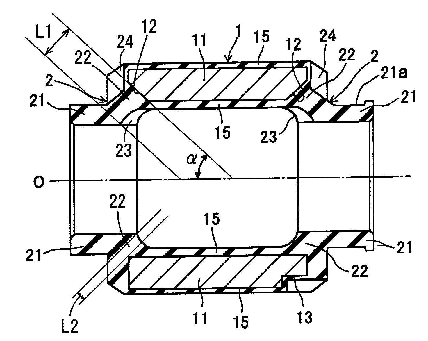
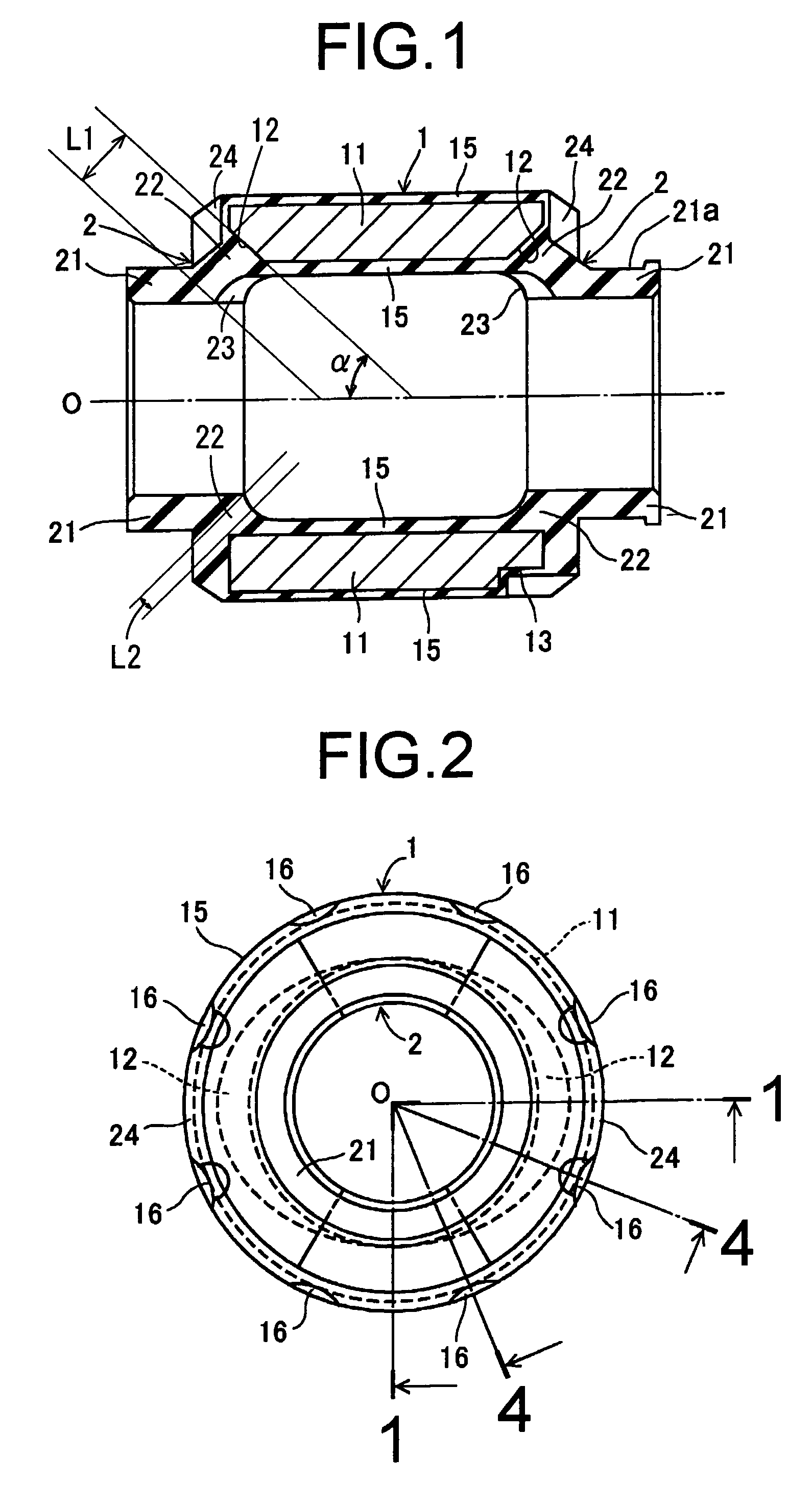
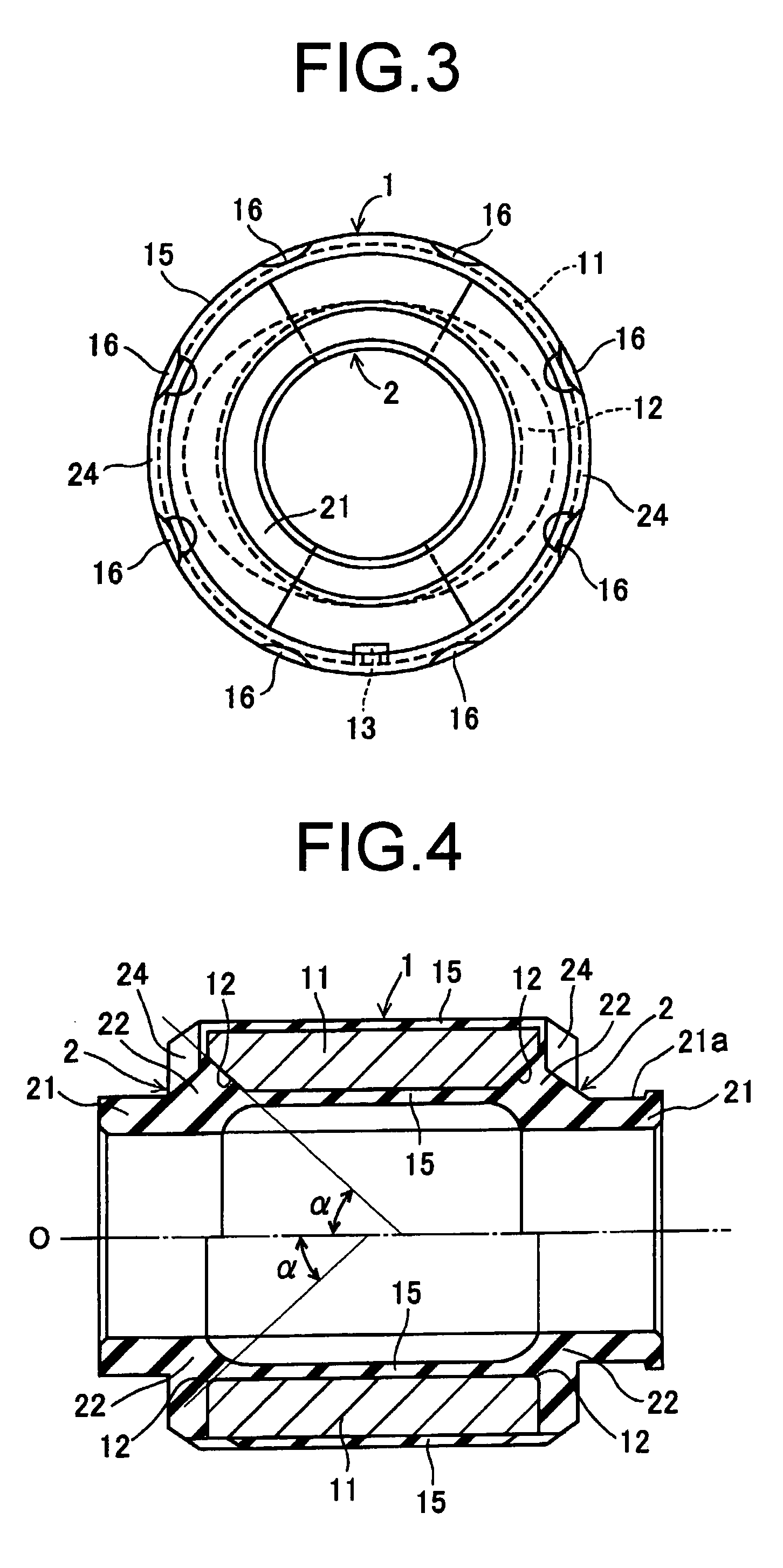
[0039]FIG. 1 is a cross sectional view of a cylindrical dynamic damper taken along the axial direction thereof, the cross section being viewed in the direction of lines 1-O-1 in FIG. 2; FIG. 2 is a left side view of the cylindrical dynamic damper; FIG. 3 is a right side view of the cylindrical dynamic damper; and FIG. 4 is a sectional view of the cylindrical dynamic damper of the embodiment, taken along the axial direction thereof, the cross section being viewed in the direction of lines 4-O-4 in FIG. 2.

[0040]As depicted in FIGS. 1-3, the cylindrical dynamic damper of this embodiment comprises: a cylindrical mass member 1 disposed spaced a distance apart from the outside peripheral side of a rotating shaft (not shown) and coaxially therewith; a pair of rubber elastic support members 2, 2 having a pair of ring-shaped affixing members 21, 21 situated at the axial ends of the mass member 1 and mounted on the outside peripheral face of the rotating shaft; a pair of elastic support port...

second embodiment

[0055]FIG. 6 is a left side view of the cylindrical dynamic damper pertaining to a second embodiment; FIG. 7 is a cross section viewed in the direction of lines 7-O-7 in FIG. 6; FIG. 8 is a right side view of the cylindrical dynamic damper; FIG. 9 is a cross section viewed in the direction of line 9-O in FIG. 6; and FIG. 10 is a cross section viewed in the direction of line 10-O in FIG. 6.

[0056]As depicted in FIG. 6-FIG. 10, the cylindrical dynamic damper of this embodiment comprises: a cylindrical mass member 1 comprising a mass body 11 and a rubber sheath layer 15; and a pair of rubber elastic support members 2, 2 having a pair of ring-shaped affixing members 21, 21 and a pair of tapered cylindrical elastic support portions 22a, 22a. While the basic design is the same as in the first embodiment, the way in which the slanted faces 12a, 12a are disposed on the inside peripheral corners of the axial ends of the mass body 11 is different. Accordingly, component parts and areas in comm...

third embodiment

[0061]FIG. 11 is a left side view of the cylindrical dynamic damper of a third embodiment; FIG. 12 is a cross section viewed in the direction of lines 12-O-12 in FIG. 11; FIG. 13 is a right side view of the cylindrical dynamic damper; FIG. 14 is a cross section viewed in the direction of line 14-O in FIG. 11; and FIG. 15 is a cross section viewed in the direction of line 15-O in FIG. 11.

[0062]As depicted in FIG. 11-FIG. 15, the cylindrical dynamic damper of this embodiment comprises a cylindrical mass member 1 comprising a mass body 11 and a rubber sheath layer 15; and a pair of rubber elastic support members 2, 2 having a pair of ring-shaped affixing members 21, 21 and a pair of tapered cylindrical elastic support portions 22b, 22b. While the basic design is the same as in the first embodiment, the way in which the slanted faces 12b, 12b are disposed on the inside peripheral corners of the axial ends of the mass body 11 is different. Accordingly, component parts and areas in common...


PUM


Abstract

A cylindrical dynamic damper including: a cylindrical mass member disposed about a rotating shaft and coaxially therewith; and a pair of elastic support members having a pair of ring-shaped affixing members situated at axial ends of the mass member and mounted on an outside peripheral face of the rotating shaft and a pair of elastic support portions of cylindrical shape connecting respectively to the affixing members and to the axial ends of the mass member to thereby elastically support the mass member. The mass member has on inside peripheral corners of both axial ends slanted faces disposed in chamfered profile and varying in shape in the circumferential direction; and the elastic support portions connected at one ends to the slanted faces have free length varying in the circumferential direction.

Description

INCORPORATED BY REFERENCE[0001]The disclosure of Japanese Patent Application No. 2005-013171 filed on Jan. 20, 2005 including the specification, drawings and abstract is incorporated herein by reference in its entirety.BACKGROUND OF THE INVENTION[0002]1. Field of the Invention[0003]The present invention relates to a cylindrical dynamic damper intended for mounting on a rotating shaft, such as an automobile drive shaft or a propeller shaft for example, in order to suppress detrimental vibration produced by the rotating shaft.[0004]2. Description of the Related Art[0005]The rotating shafts, such as an automobile drive shaft or a propeller shaft, may experience undesired detrimental vibration such as bending vibration or twisting vibration due to rotational unbalance produced in association with rotation thereof. In order to suppress such detrimental vibration, dynamic dampers of various kinds are employed. A dynamic damper achieves its function by means of matching its resonance frequ...

Claims


Application Information

Patent Timeline
Patent Type & Authority Patents(United States)
IPC IPC(8): F16F7/00F16M13/00
CPCF16F15/1442
Inventor HAYASHI, TAKASHIKUWAYAMA, NAOHITO
Owner SUMITOMO RIKO CO LTD
Why Eureka
Try Eureka