
Electrical connector

a technology of electrical connectors and connectors, applied in the direction of securing/insulating coupling contact members, electrical discharge lamps, coupling device connections, etc., can solve the problems of contradicting space-saving two-point contact, and achieve the effect of improving connection stability, reducing overall height, and superior vibration resistan

Inactive Publication Date: 2009-12-22
DDK LTD
View PDF6 Cites 23 Cited by
  • Summary
  • Abstract
  • Description
  • Claims
  • Application Information

AI Technical Summary

Benefits of technology

"The invention is an electrical connector that solves problems with previous connectors by being resistant to vibration, space-saving, and having a reduced overall height. The connector has a plug and receptacle connector that are detachably fitted together. The receptacle connector has multiple receptacle contacts with a first contact portion adapted to make contact with a mating contact, a first fixed portion to be fixed to a block, and a first connection portion to be connected to a substrate. The plug connector has multiple plug contacts with a second contact portion adapted to make contact with the receptacle contacts, second and third fixed portions to be fixed to a housing and an insulator, and a second connection portion to be connected to a substrate. The plug contacts have an elastic portion with at least one snaked portion and the insulator is held in a floating state in the housing. The elastic portion is positioned such that its upper and lower curved portions are at the same height as the second and first contact portions of the receptacle contacts. The receptacle contacts also have a third contact portion to contact the elastic portion. The connector is designed to improve connection stability and reduce overall size."

Problems solved by technology

However, in order to achieve the space-saving (miniaturized width dimension), thicknesses of walls must be thinner as much as possible, while for the purpose of improving the resistance to vibration, the thicknesses of the walls must be thicker as much as possible so that the contradictory problems remain to be solved.
However, the two-point contact would be contradicting the space-saving.

Method used


Image

  • Electrical connector
  • Electrical connector
  • Electrical connector

Examples


Embodiment Construction

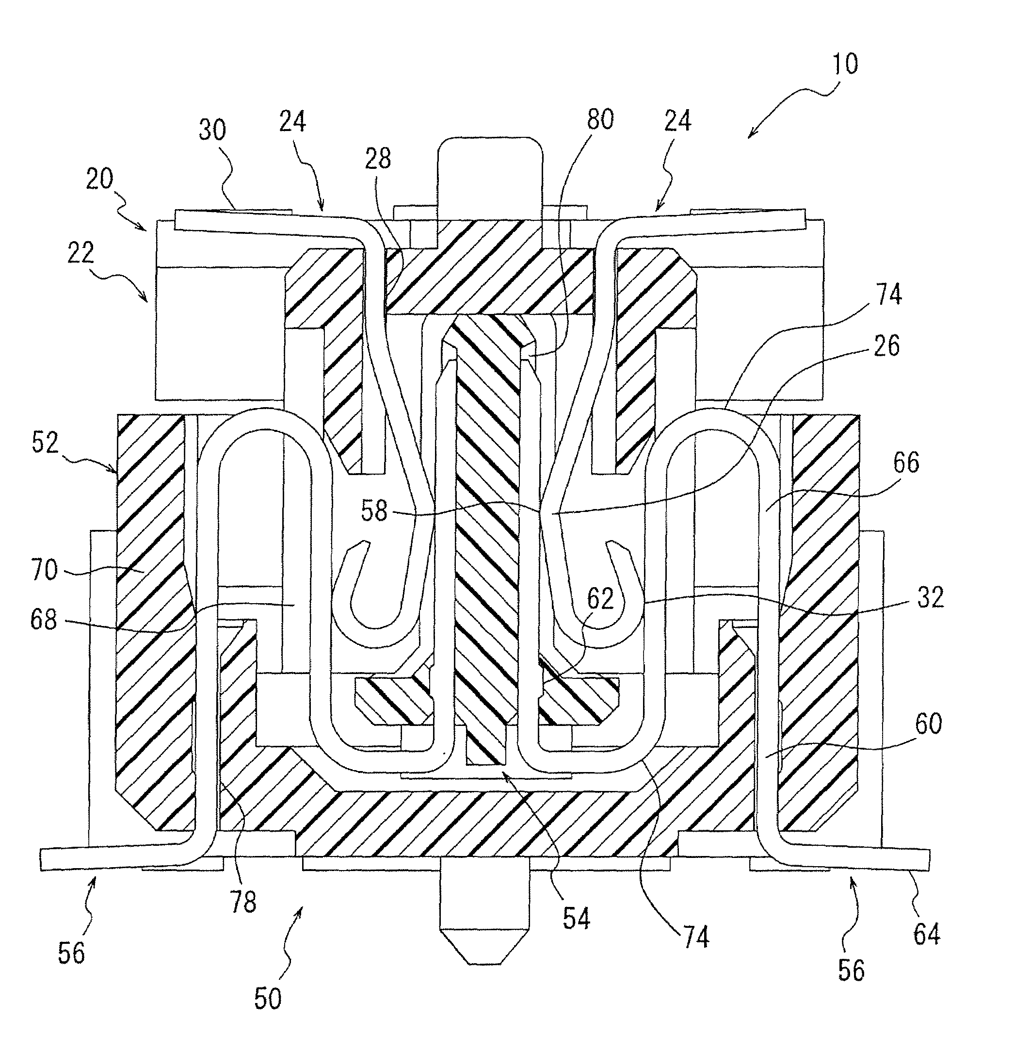
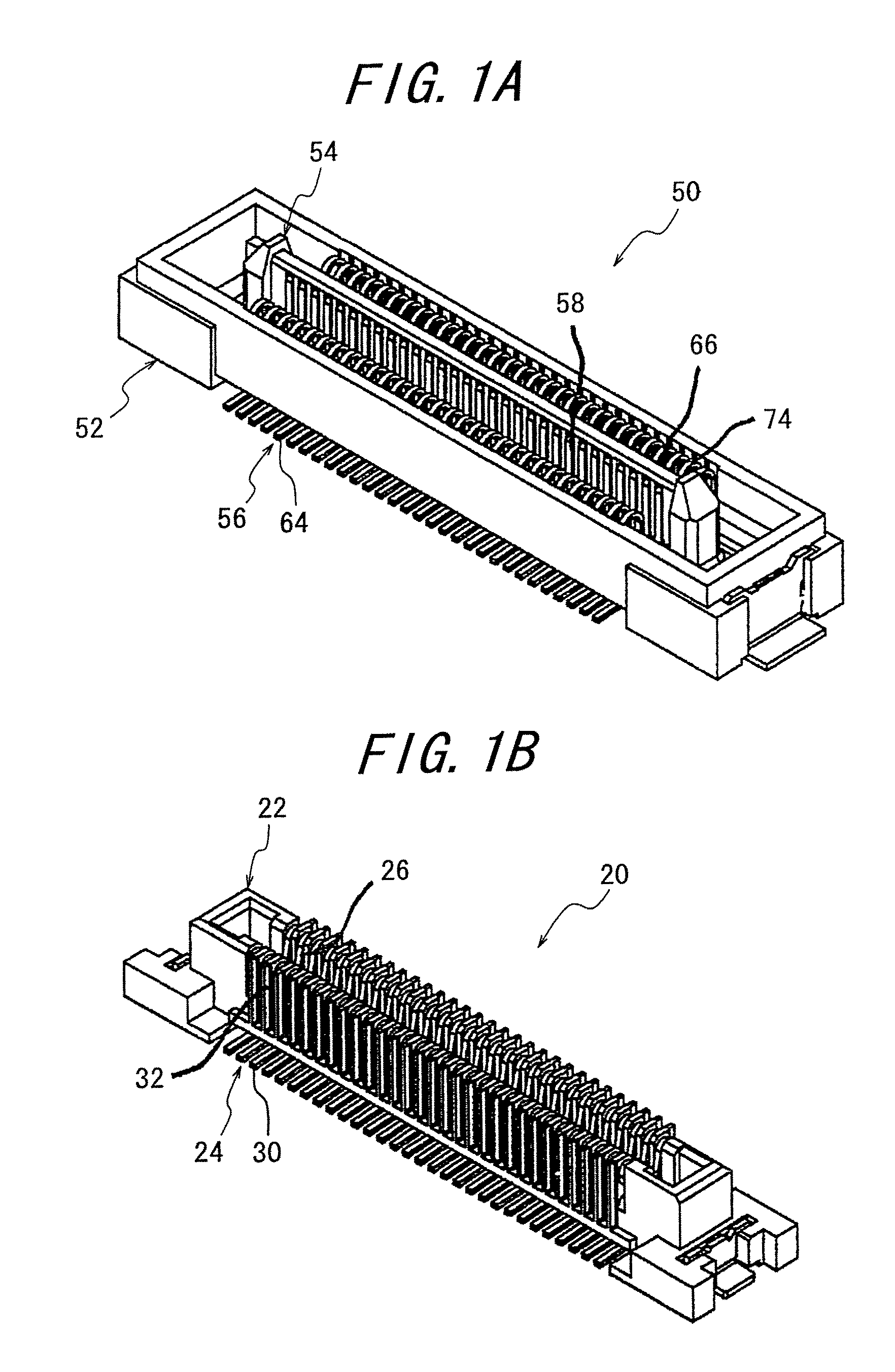
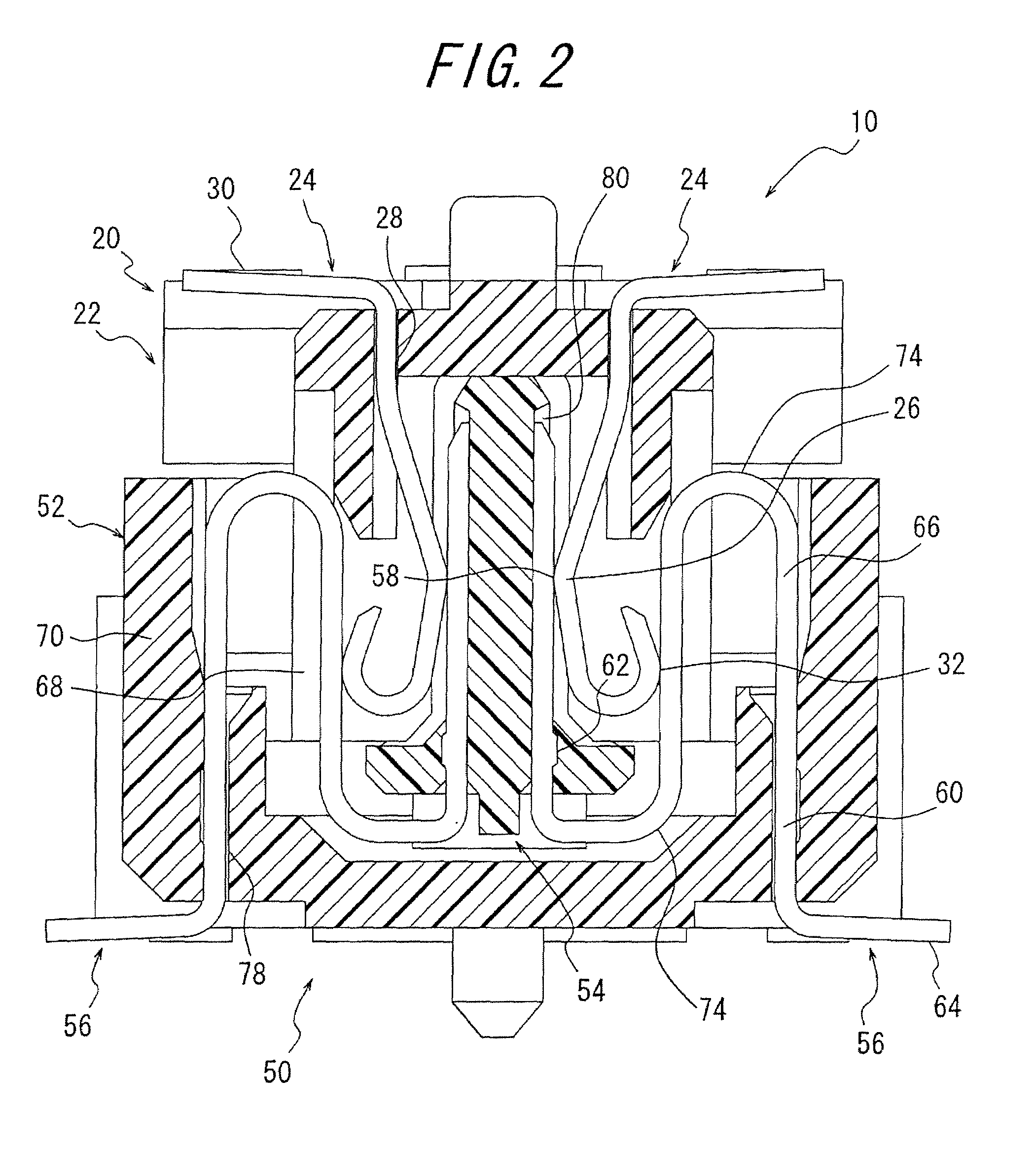
[0038]The important aspect of the invention lies in the electrical connector 10 consisting of a plug connector 50 and a receptacle connector 20 detachably fitted with each other, said receptacle connector 20 including a plurality of receptacle contacts 24 each having a first contact portion 26 adapted to contact a mating contact, a first fixed portion 28 to be fixed to a block 22, and a first connection portion 30 to be connected to a substrate 90, and the block 22 for arranging and holding said receptacle contacts 24, and said plug connector 50 including a plurality of plug contacts 56 each having a second contact portion 58 adapted to contact said receptacle contact 24, second and third fixed portions 60 and 62 to be fixed to a housing 52 and an insulator 54, respectively, and a second connection portion 64 to be connected to a substrate 90, and the housing 52 and the insulator 54 for arranging and holding said plug contacts 56, wherein each of said plug contacts 56 is provided be...


PUM


Abstract

An electrical connector consists of a plug connector and a receptacle connector to be fitted. An insulator is supported only by plug contacts each having an elastic portion between second and third fixed portions so as to be floating in a housing. The elastic portion is so positioned that its upper curved portion is at the same height as a second contact portion and its lower curved portion is at the same height as the lower end of the insulator. The distal end of a first contact portion of a receptacle contact is folded back toward a first connection portion to provide a third contact to contact the elastic portion so that the first contact portion and the third contact portion of the receptacle contact and the second contact portion and the elastic portion of the plug contact are caused to contact each other in line contacts at two locations. The electrical connector thus constructed is superior in resistance to vibration, and achieves space-saving and a reduced overall height less than 5 mm and further the floating of the insulator.

Description

BACKGROUND OF THE INVENTION[0001]This invention relates to an electrical connector for use in electric and electronic appliances such as industrial machines, car navigation systems, and the like, and more particularly to an electrical connector superior in resistance to vibration and enabling floating of a part in the connector even when a space-saving is achieved (width dimension in a fitted state being less than 5 mm).[0002]In hitherto used electrical connectors having a floating part, two insulators have often been used, either of which is supported only by contacts having an elastic portion which is elastically deformable. It has been found that in order to provide an elasticity to contacts, elastic portions of the contacts are snaked or curved, or the contacts are elongated by increasing a distance between two insulators.[0003]As examples of prior art electrical connectors, incorporated herein are Japanese Patent Application Opened No. 2002-42,937 (Patent Literature 1), Japanes...

Claims


Application Information

Patent Timeline
Patent Type & Authority Patents(United States)
IPC IPC(8): H01R13/52H01R12/73
CPCH01R12/716H01R13/41H01R13/6315H01R12/91
Inventor FUKAZAWA, TAKEKIYOSHIMI, TAKANOBU
Owner DDK LTD
Features
  • Generate Ideas
  • Intellectual Property
  • Life Sciences
  • Materials
  • Tech Scout
  • Unparalleled Data Quality
  • Higher Quality Content
  • 60% Fewer Hallucinations
Learn More