Combined switch

a combined switch and switch technology, applied in the direction of switch side location, camera, electrical equipment, etc., can solve the problem of inhibiting the miniaturization of the combined switch, and achieve the effect of minimizing the combined switch

Active Publication Date: 2009-12-22
HOSIDEN CORP
View PDF12 Cites 14 Cited by
  • Summary
  • Abstract
  • Description
  • Claims
  • Application Information

AI Technical Summary

Benefits of technology

[0009]In view of the above, it is an object of the present invention to provide a combined switch which is capable of achieving easy assembly and a decrease in mounting area.
[0021]In the rotary switch mounted in the conventional combined switches disclosed above, one common fixed contact for the rotary switch is disposed on the circumference of a circle and other fixed contacts (individual contacts) are disposed on the circumference of a different circle. Therefore, in order to constitute the rotary switch, an additional area corresponding to an outside circle making up the double circles is required, which causes a limit to the miniaturization of the combined switch. However, according to the present invention, contacts for the rotary switch are formed on the circumference of the same circle. Therefore, unlike in the conventional technology, when the rotary switch is constituted, no additional area corresponding to the outside circle making up the double circles is required, thus enabling the miniaturization of the combined switch. As a result, the combined switch having a less mounting area can be provided.
[0022]Moreover, the body portion includes fixed contacts for the push switch and the rotary switch, and houses movable contacts for the push switch and the rotary switch. The fixed contacts and movable contacts are positioned within the main body portion, thereby making it easy to assemble the combined switch.
[0024]A plurality of contactors of the brush is formed on the circumference of the same circle in a manner to correspond to contacts for the rotary switches disposed on the circumference of the same circle. The brush of the conventional combined switch has contactors for contacts on a circle on an inner circumference side and contactors for contacts on a circle on an outer circumference side in a manner to correspond to contacts having a concentric circle shape. According to the present invention, the two contactors out of a plurality of contactors formed on the circumference of the same circle are made to provide concurrent functions of contacting with the common contacts and contacting with individual contacts. Therefore, it is made possible to effectively bring the common contacts and individual contacts into conduction on the circumference of the same circle, thus achieving the miniaturization of the combined switch.
[0033]By configuring as above, the leg portions of the upper electrode plate and the fixed portion are placed so as to overlap in a direction of a pressing operation on the push switch. Therefore, the combined switch can be configured without being extended in a diameter (horizontal) direction of the rotary switch. As a result, the miniaturization of the combined switch can be achieved.

Problems solved by technology

As a result, in order to constitute the rotary switch, an additional area corresponding to an outside circle making up the double circles is required, which inhibits the miniaturization of the combined switch.

Method used


Image

  • Combined switch
  • Combined switch
  • Combined switch

Examples


Embodiment Construction

[0047]Best modes of carrying out the present invention will be described in further detail using embodiments with reference to the accompanying drawings.

One Embodiment

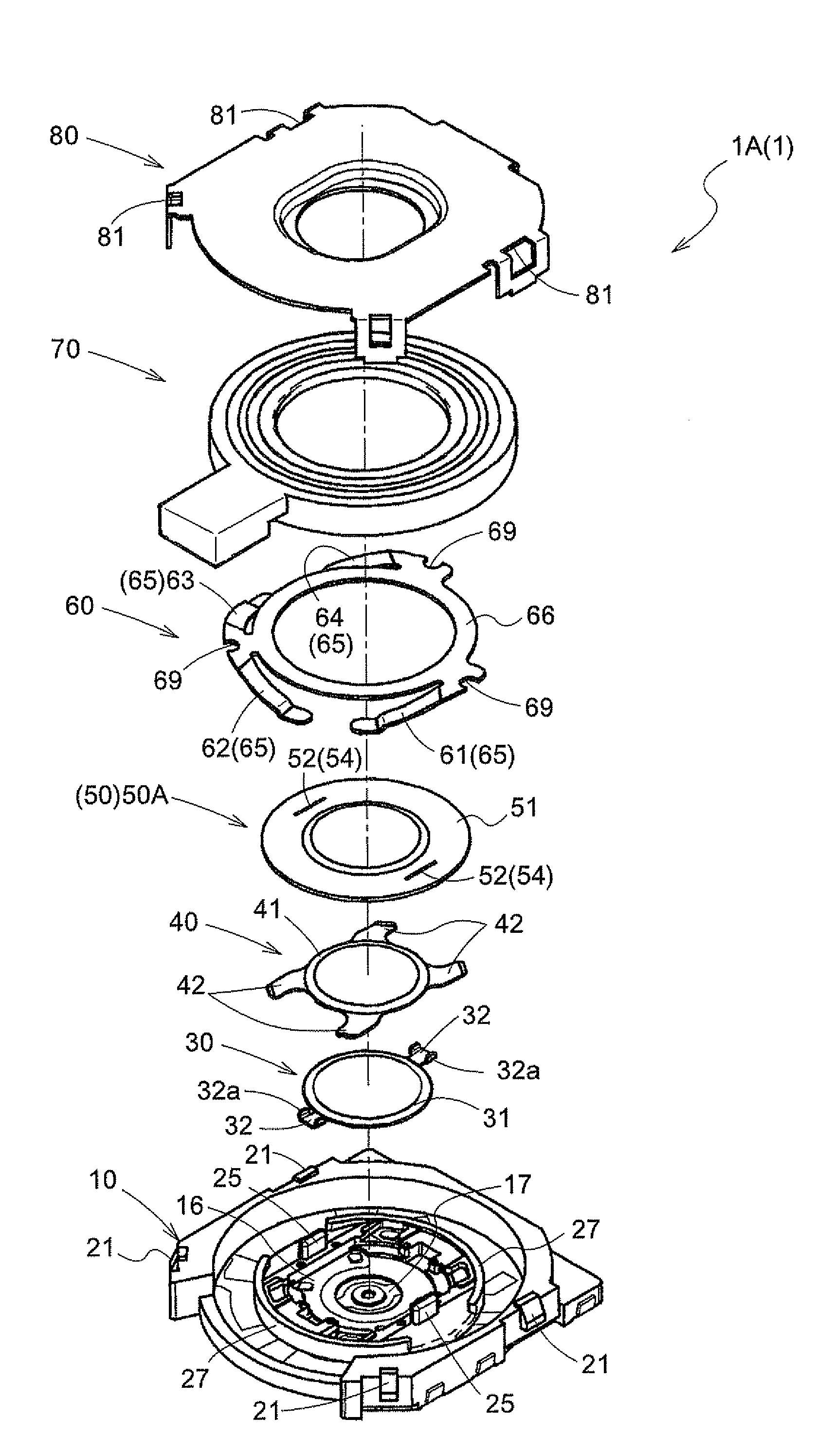
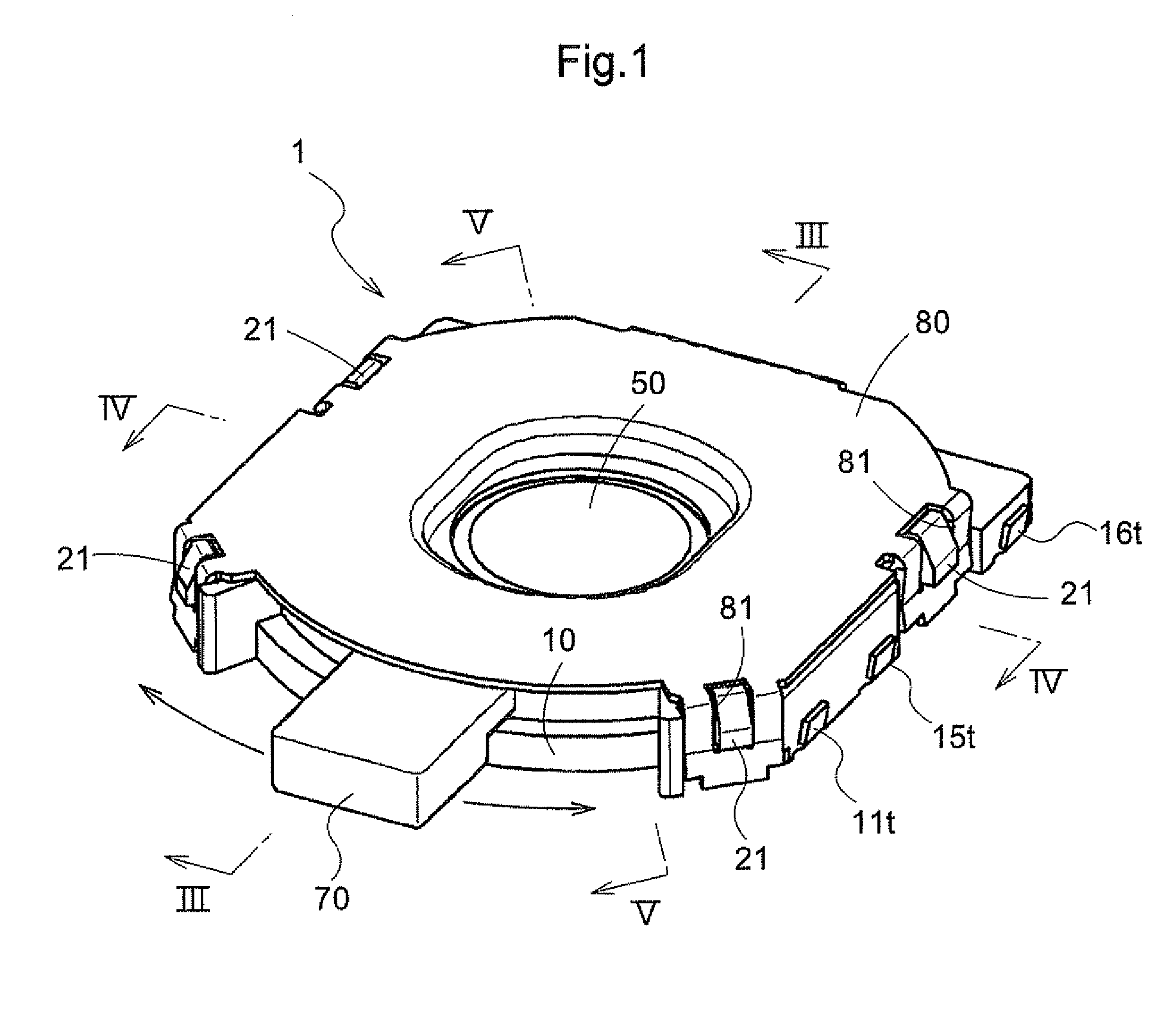
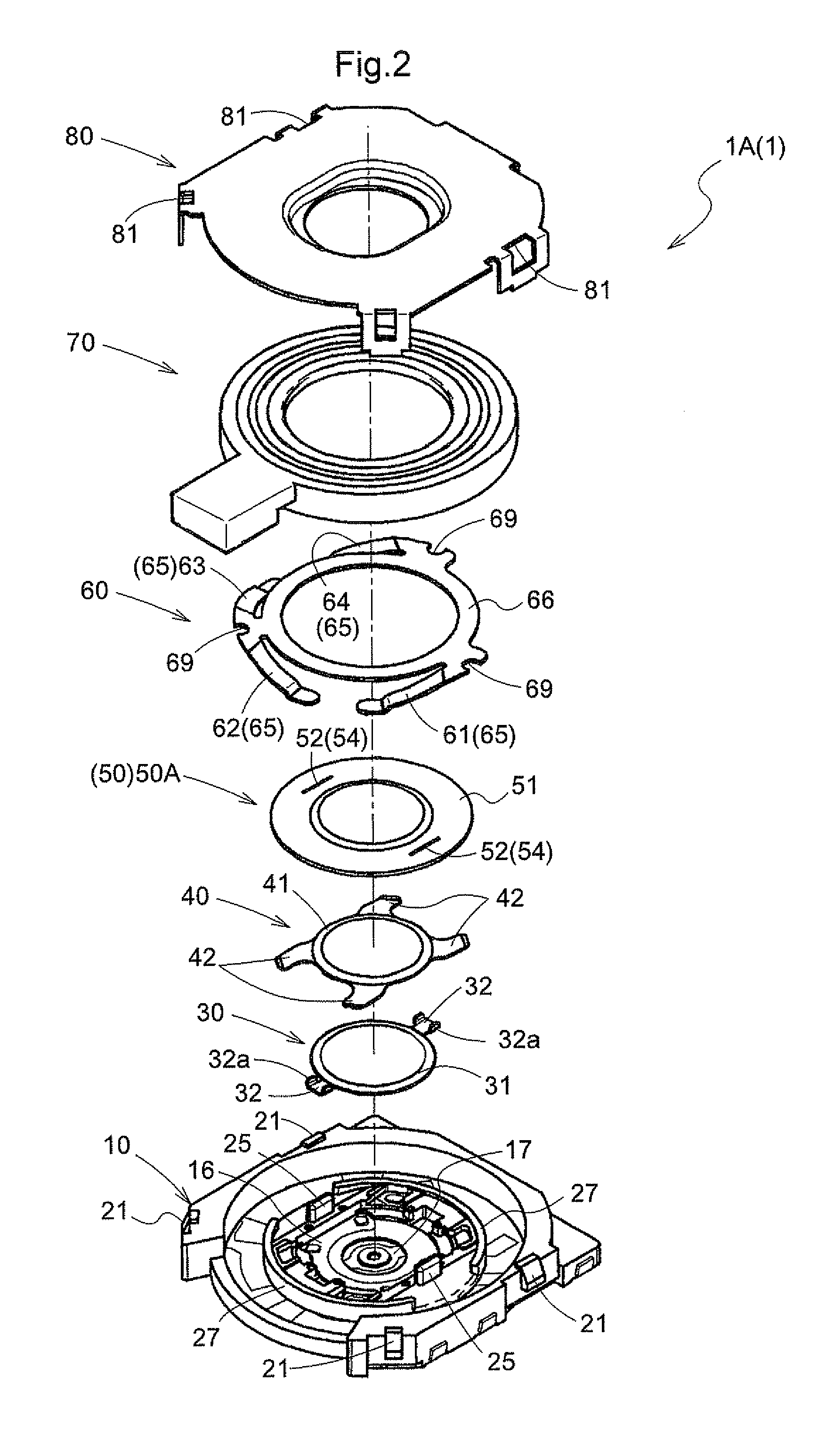
[0048]FIG. 1 is a perspective view showing a combined switch of an embodiment of the present invention. FIG. 2 is an exploded perspective view of the combined switch of the embodiment of the present invention. FIGS. 3 to 5 are a cross-sectional view of the combined switch of FIG. 1.

[0049]The combined switch 1 (1A) is a switch obtained by combining a push switch to be activated by a pressing operation and a rotary switch to be activated by a rotating operation. The combined switch 1 is mounted, for example, on a circuit board of a digital camera or a like and is configured to be covered by exterior components thereof. The exterior components make up an operating section having, for example, a mode switching function, zoom switching function, and shouter function in a combined manner.

[0050]As shown in FIG. 2 the combined...


PUM


Abstract

A main body portion has fixed contacts and houses movable contacts. A lower electrode plate and upper electrode plate serving as the movable contacts are deformed at a time of a pressing operation. The upper electrode plate is contactable to the lower electrode plate and lower electrode plate brings contact pairs mounted in a center of the bottom inside the main body portion into conduction. On the bottom inside the main body portion, contacts serving as fixed contacts for a rotating operation are formed on the circumference of the same circle outside contact pairs for the pressing operation. A brush serving as the movable contacts is secured to a lever receiving rotating operational forces and brings contacts into conduction.

Description

BACKGROUND OF THE INVENTION[0001]1. Field of the Invention[0002]The present invention relates to a combined switch obtained by combining a push switch to be activated by a pressing operation and a rotary switch by a rotating operation.[0003]2. Description of the Related Art[0004]A conventional combined switch is already known which has tried to achieve a decrease in a component count and mounting area by providing the switch with a plurality of switch functions. Such a combined switch is used for the integration of a photographic mode changing switch and / or zoom switch with a shutter, for example, in a film camera, digital camera, or a like.[0005]Such combined switches as above are disclosed in, for example, JP2000-331569 (Patent Reference 1, 18th to 26th paragraphs and the like) and JP11-306918A (Patent Reference 2, 12th to 23rd paragraphs and the like).[0006]The combined switch disclosed in the Patent Reference 1 is realized by combining a tactile switch (push switch) and a rotary...

Claims


Application Information

Patent Timeline
Patent Type & Authority Patents(United States)
IPC IPC(8): H01H19/58
CPCH01H13/64H01H19/003H01H25/008H01H19/58H01H2227/036H01H2231/046H01H2225/018H01H13/14H01H13/26H01H13/48H01H19/02H01H25/06H01H2025/043
Inventor ASADA, MAKOTO
Owner HOSIDEN CORP
Why Eureka
Try Eureka