Flow meter and flow-regulating system using the same

a flow meter and flow regulating technology, applied in the direction of volume metering, process and machine control, instruments, etc., can solve the problems of generating bubbles, affecting the accuracy of flow-rate measurement, and the inability to drill one process through an entire channel, so as to prevent or suppress the generation of bubbles, and maintain the performance of the motor for a long period of time.

Active Publication Date: 2009-12-29
SURPASS IND
View PDF10 Cites 10 Cited by
  • Summary
  • Abstract
  • Description
  • Claims
  • Application Information

AI Technical Summary

Benefits of technology

[0009]Because of this situation, there is a demand for the development of a flow meter that is capable of preventing or suppressing the generation of bubbles and maintaining sufficient measurement accuracy in a minute flow rate area, and that is less likely to cause accumulation of fluid and bubbles.
[0068]With the flow-rate control system according to the present invention, the position of the valve element the flow-rate control valve can be accurately determined without using an expensive rotary encoder.

Problems solved by technology

The above-described known differential-pressure flow meter has a problem in that when it is disposed in the fluid channel whose outlet side is open to the atmosphere, bubbles are generated at the downstream side (the secondary side) throttled by the orifice.
Since the generated bubbles tend to accumulate at the pressure sensor disposed on the secondary side and flow out as a cluster after accumulating, the generation of such bubbles not only negatively affects the flow-rate measurement accuracy, particularly in a minute flow-rate region, but also causes a problem in that, if the fluid channel is a wafer cleaning line in a semiconductor production apparatus, the products are negatively affected by a cleaning solution containing bubbles generated at the differential-pressure flow meter pouring onto the wafer.
However, when the channel is curved, the entire channel cannot be formed by one drilling process.
However, in a body having such a structure, since spaces are created in sections other than the channel where the holes are buried, the fluid tends to accumulate in these spaces.

Method used


Image

  • Flow meter and flow-regulating system using the same
  • Flow meter and flow-regulating system using the same
  • Flow meter and flow-regulating system using the same

Examples


first embodiment

[0081]A flow meter according to a first embodiment of the present invention will be described below with reference to the drawings.

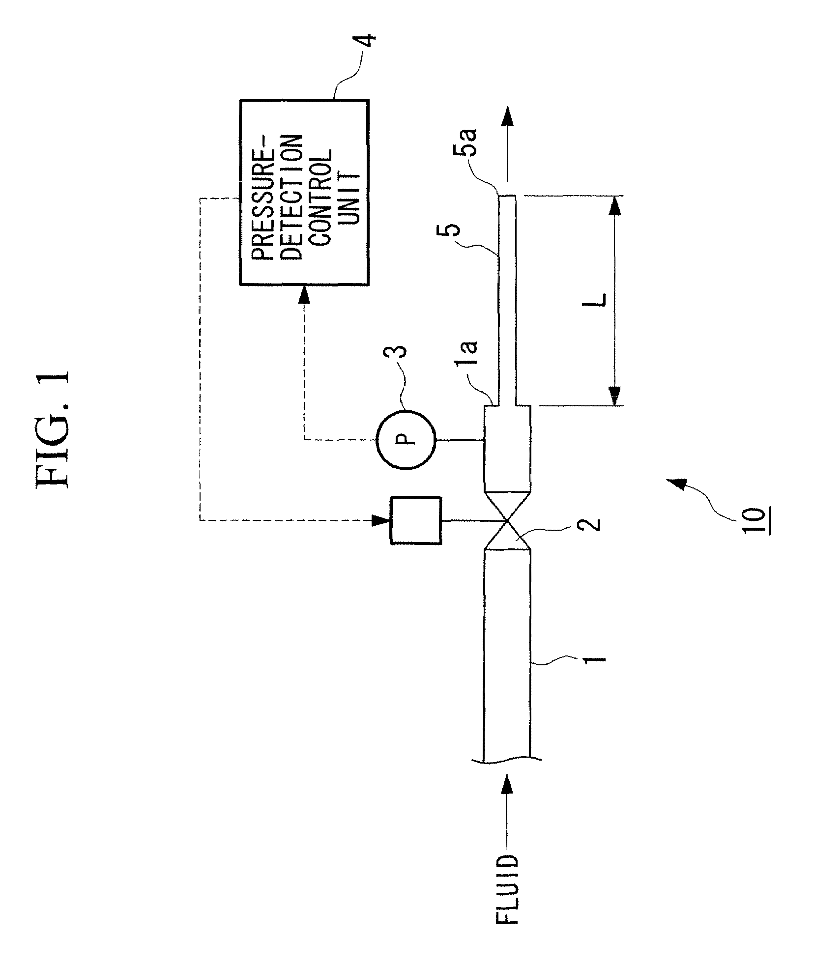
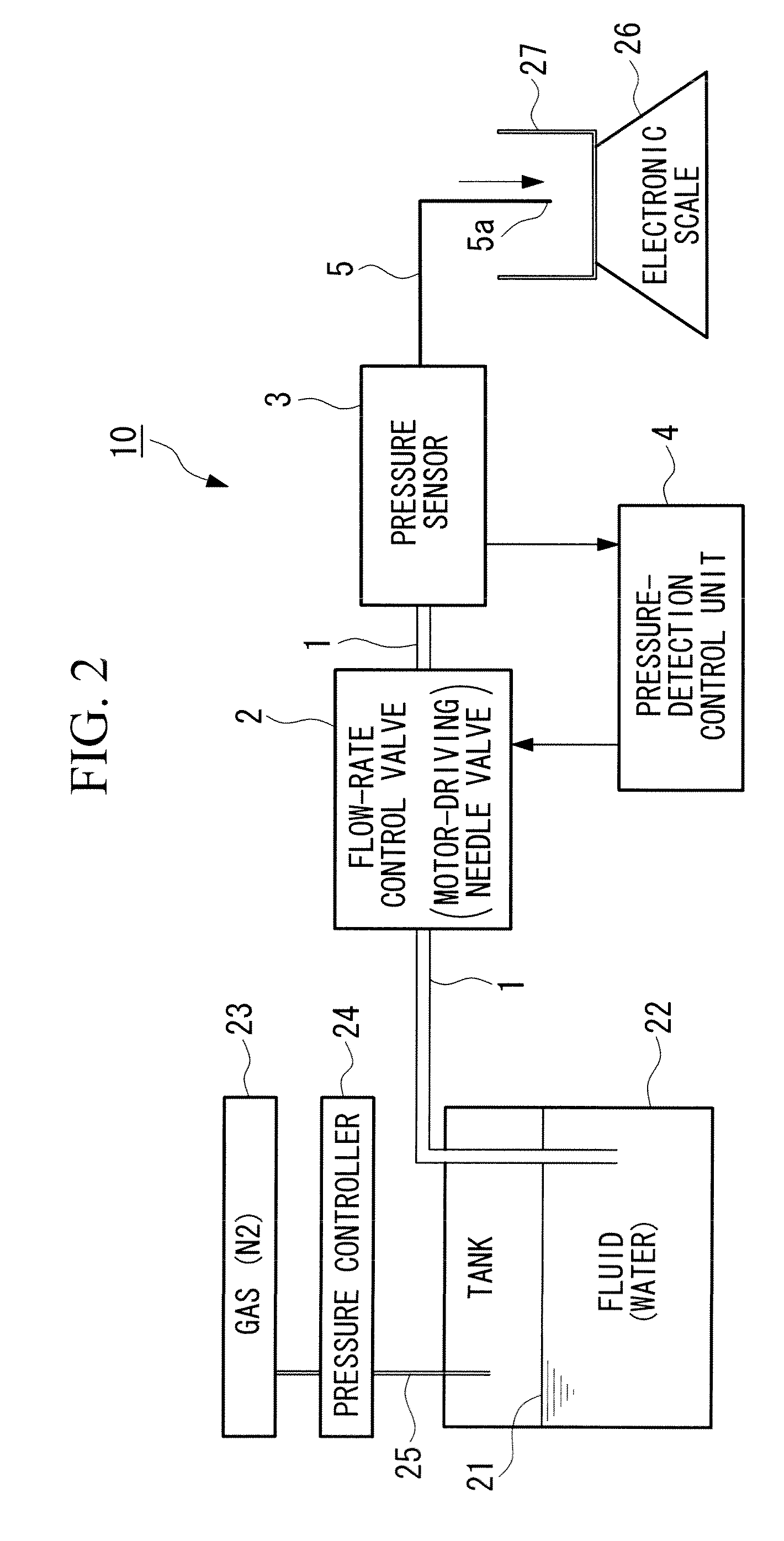
[0082]FIG. 1 is a diagram showing the configuration of the flow meter according to this embodiment. This flow meter 10 measures a minute flow rate of a fluid flowing through a fluid channel 1 having an outlet open to the atmosphere. Near an end section 1a on the outlet side of the fluid channel 1, a flow-rate control valve 2 for controlling the flow rate of a fluid by adjusting the degree of opening and a pressure sensor 3 that is pressure detection part for detecting the pressure of the fluid are provided. The fluid pressure detected by the pressure sensor 3 is input to a pressure-detection control unit (hereinafter referred to as a “control unit”) 4 that is pressure / flow-rate conversion part. Here, the pressure sensor 3 to be employed is not limited, so long as it is capable of detecting the fluid pressure; however, for example, a piezoelectric pressur...

second embodiment

[0119]An embodiment of a flow-rate control system according to the present invention will be described below with reference to the drawings.

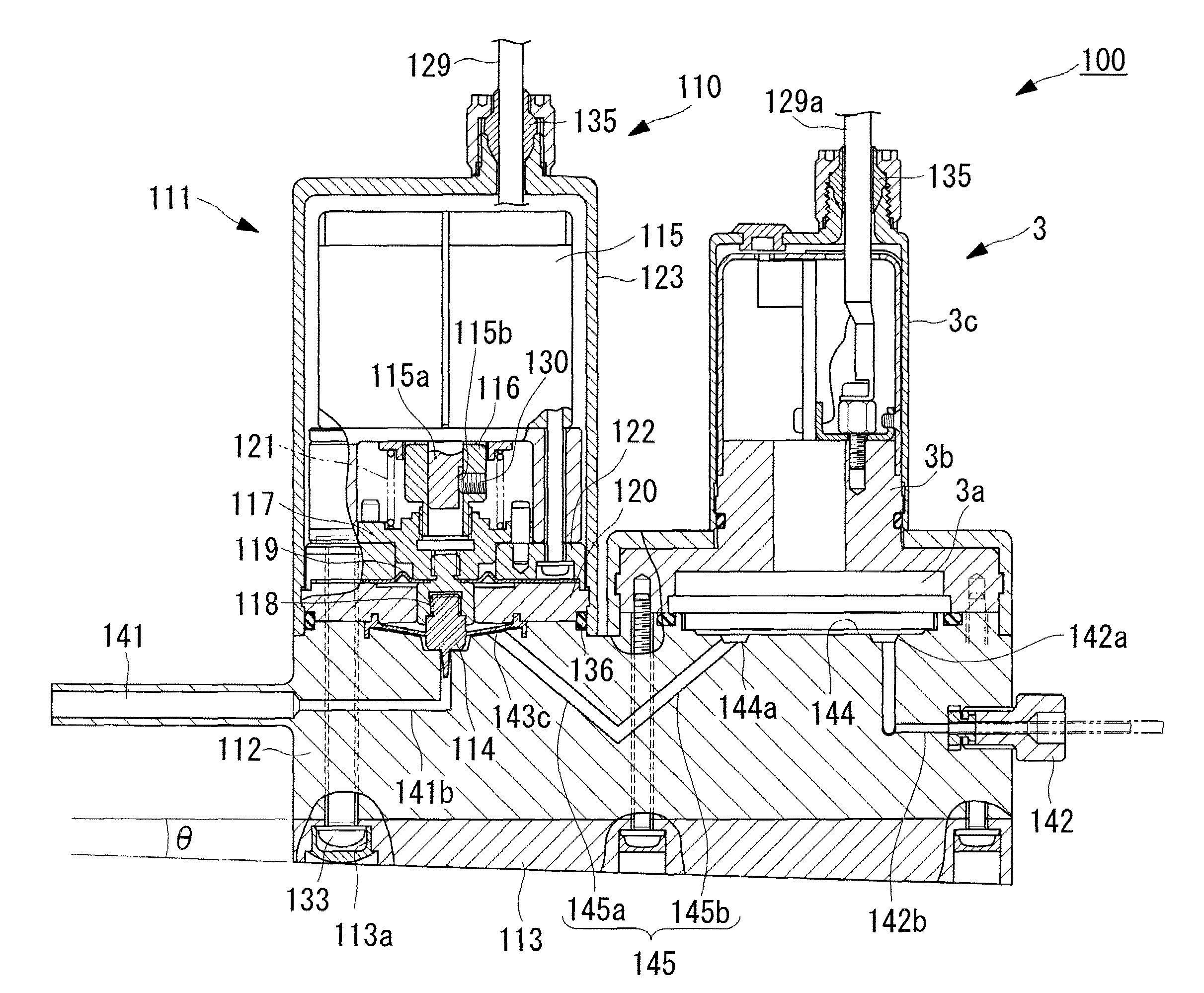
[0120]As shown in FIG. 4, a flow-rate control system 100 according to this embodiment is characterized in that, in the flow meter 10 according to the first embodiment, a flow-rate control valve 110 is used instead of the flow-rate control valve 2, and this flow-rate control valve 110 and the flow meter 10 are provided on a surface (upper surface in this embodiment) of a block-shaped body 112 having a fluid channel 101 inside.

[0121]Hereinafter, components that are similar to or the same as those in the flow meter 10 according to the first embodiment are assigned the same reference numerals, and descriptions thereof are omitted.

[0122]The flow-rate control valve 110 is constituted mainly of a driving unit 111, the body 112, a base 113 (pedestal), and a diaphragm needle (valve element) 114.

[0123]The driving unit 111 includes a motor 115, a coupling ...

third embodiment

[0185]Another embodiment of a flow-rate control system according to the present invention will be described with reference to FIG. 6.

[0186]The flow-rate control system according to this embodiment is mainly characterized in that in the flow-rate control system 100 according to the second embodiment, instead of the flow-rate control valve 110, a flow-rate control valve 150 is used. The flow-rate control valve 150 differs from that according to the second embodiment in that, instead of the spring 121, a spring 151 is provided. Since the other components are the same as those according to the above-described second embodiment, descriptions thereof are omitted.

[0187]The same members as this according to the above-described second embodiment are represented by the same numerals.

[0188]The spring 151 according to this embodiment is a compression coil spring interposed between the slider 117 and the cover flange 122 and constantly urges the slider 117 upward (toward the motor 115). In this ...


PUM


Abstract

Provided are a flow meter and a flow-rate control system using the same that is capable of measuring a flow rate in a minute flow-rate region with excellent measurement accuracy by preventing or suppressing the generation of bubbles and in which accumulation of the fluid and the bubbles is less likely to occur. The flow meter is for measuring a minute flow rate of a fluid flowing through a fluid channel whose outlet environment is set to constant pressure, the flow meter including a flow-rate measurement conduit portion having a predetermined length connected to an outlet-side end of the fluid channel 1 and whose outlet environment is set to constant pressure by setting the cross-sectional area of a channel smaller than the fluid channel; a pressure sensor for detecting the pressure of the fluid at the upstream side of the flow-rate measurement conduit portion by being disposed near an outlet of the fluid channel 1; and a pressure-detection control unit 4 for calculating a flow rate from a fluid pressure detected at the pressure detection part.

Description

CROSS-REFERENCE TO RELATED APPLICATIONS[0001]This application is a National Phase Application based upon and claiming the benefit of priority to PCT / JP2006 / 307060, filed on Apr. 3, 2006, which is based upon and claims the benefit of priority to Japanese Patent Application No. 2005-167073, filed Jun. 7, 2005, the contents of both of which are incorporated herein by reference.TECHNICAL FIELD[0002]The present invention relates to a flow meter used for controlling chemical injection at a minute flow rate in, for example, a wafer cleaning line of a semiconductor production apparatus and relates to a flow-rate control system using the same.BACKGROUND ART[0003]In the past, flow meters, connected in-line to a fluid circuit, for measuring the flow rate of a fluid flowing through a channel have been widely adopted. Known examples of such flow meters include meters provided with an orifice, a Venturi nozzle, a pilot tube and the like installed in an appropriate location in the channel and that...

Claims


Application Information

Patent Timeline
Patent Type & Authority Patents(United States)
IPC IPC(8): G01F5/00F16K17/00
CPCG01F1/42G05D7/0635G01F1/48Y10T137/87217Y10T137/7725G01F15/005G01F1/363G01F25/10G01F1/34G05D7/06
Inventor USHIGUSA, YOSHIHIROIGARASHI, HIROKIHASUNUMA, MASAHIRO
Owner SURPASS IND
Why Eureka
Try Eureka