Low profile over-under conveyor

a conveyor and low profile technology, applied in the direction of mechanical conveyors, furnaces, charge manipulation, etc., can solve the problems of requiring precise alignment, requiring vertical height of conveyors, and more difficult to load and unload conveyers

Inactive Publication Date: 2009-12-29
ZETA GRP MFG LLC +1
View PDF9 Cites 40 Cited by
  • Summary
  • Abstract
  • Description
  • Claims
  • Application Information

AI Technical Summary

Benefits of technology

[0007]The present invention relates to a low profile, over-under conveyor with two continuously moving chain loops that form upper and lower tracks on which flexible work platforms ride. Each flexible platform includes two or more spaced metal slats joined by a thin flexible band. The slats include shoes that rest on and frictionally engage the moving chain loops. When one of the platforms reaches the end of one track, the flexible platform frictionally engages and compresses a pneumatic drive wheel and flexes to negotiate a low profile inversion and return on the other track. This allows the conveyor to handle long work platforms, while having a relatively low profile. Asynchronous accumulation and release of the freely moving flexible work platforms is accomplished using stop cylinders mounted inside the frame of the conveyor.
[0008]One advantage of the present over-under conveyor invention is its low profile. The conveyor requires less than six inches of vertical clearance from the floor to the center line of its drive and driven shafts. Thin three inch wide slats joined by a thin flexible band create a flexible work platform that can negotiate a tight rotation around the relatively small diameter drive wheels. The resulting low profile over-under conveyer can be installed close to the ground for easy loading and unloading of the conveyor. The low profile over-under conveyor can also be installed close to a ceiling so that it will minimize or eliminate interference with other work being done in and around the conveyor.
[0009]Another advantage of the present low profile over-under conveyor is the unique simplicity of its design. The conveyer requires no special attachments to the pallets to drive them from the upper level to the lower level or vice versa and has a very smooth operation.
[0010]A further advantage of the present low profile over-under conveyor is its reliability. The flexible frictional engagement between the compressible pneumatic drive wheels and the flexible belt of the platforms is very forgiving. There are no special alignment concerns that must be maintained to properly operate the conveyor to prevent jamming and the shut down of the conveyor.

Problems solved by technology

A problem with conventional over / under conveyor designs is the vertical height require by the conveyor to invert their pallets or work platforms.
Yet, higher clearances can make it more difficult to load and unload the conveyer, particularly when bulky, heavy or awkward workpieces are being moved.
Another problem with conventional conveyors is they require precise alignment, particularly with respect to the pallet or work platform inversion mechanisms at the ends of the conveyor.
For example, the '058 design requires highly machined and complicated components, such as split disc tapered gripper mechanisms.
Slight misalignments and normal wear and tear can jam the conveyers and result in costly shut downs.
Jamming is particularly troublesome with positive engagement inversion systems like the '933 deign which can bind and jam during use.
Conveyor shut downs are particularly problematic because they can negatively impact an entire manufacturing operation.
Another problem with conventional over / under conveyor designs is the complexity of their design.
The designs are also costly to manufacture and service.

Method used


Image

  • Low profile over-under conveyor
  • Low profile over-under conveyor
  • Low profile over-under conveyor

Examples


Embodiment Construction

[0021]While this invention is susceptible of embodiment in many different forms, the drawings show and the specification describes in detail a preferred embodiment of the invention. It should be understood that the drawings and specification are to be considered an exemplification of the principles of the invention. They are not intended to limit the broad aspects of the invention to the embodiment illustrated.

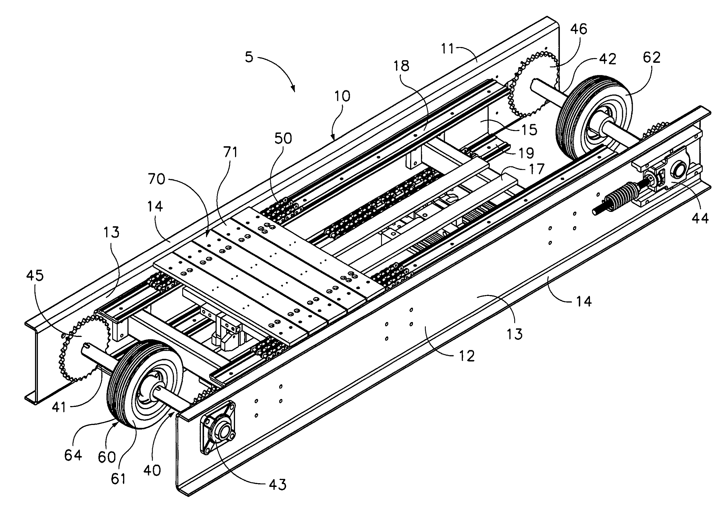
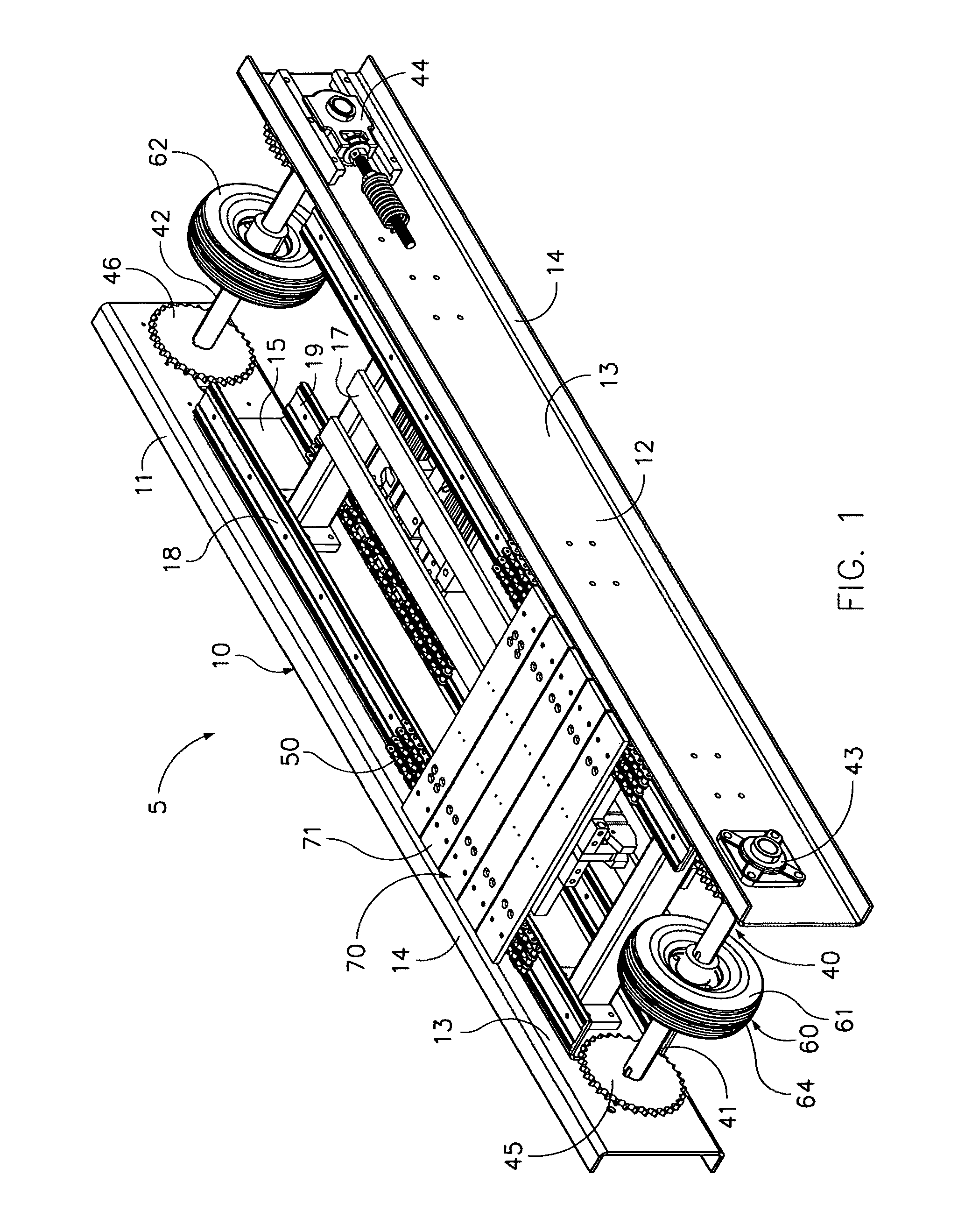
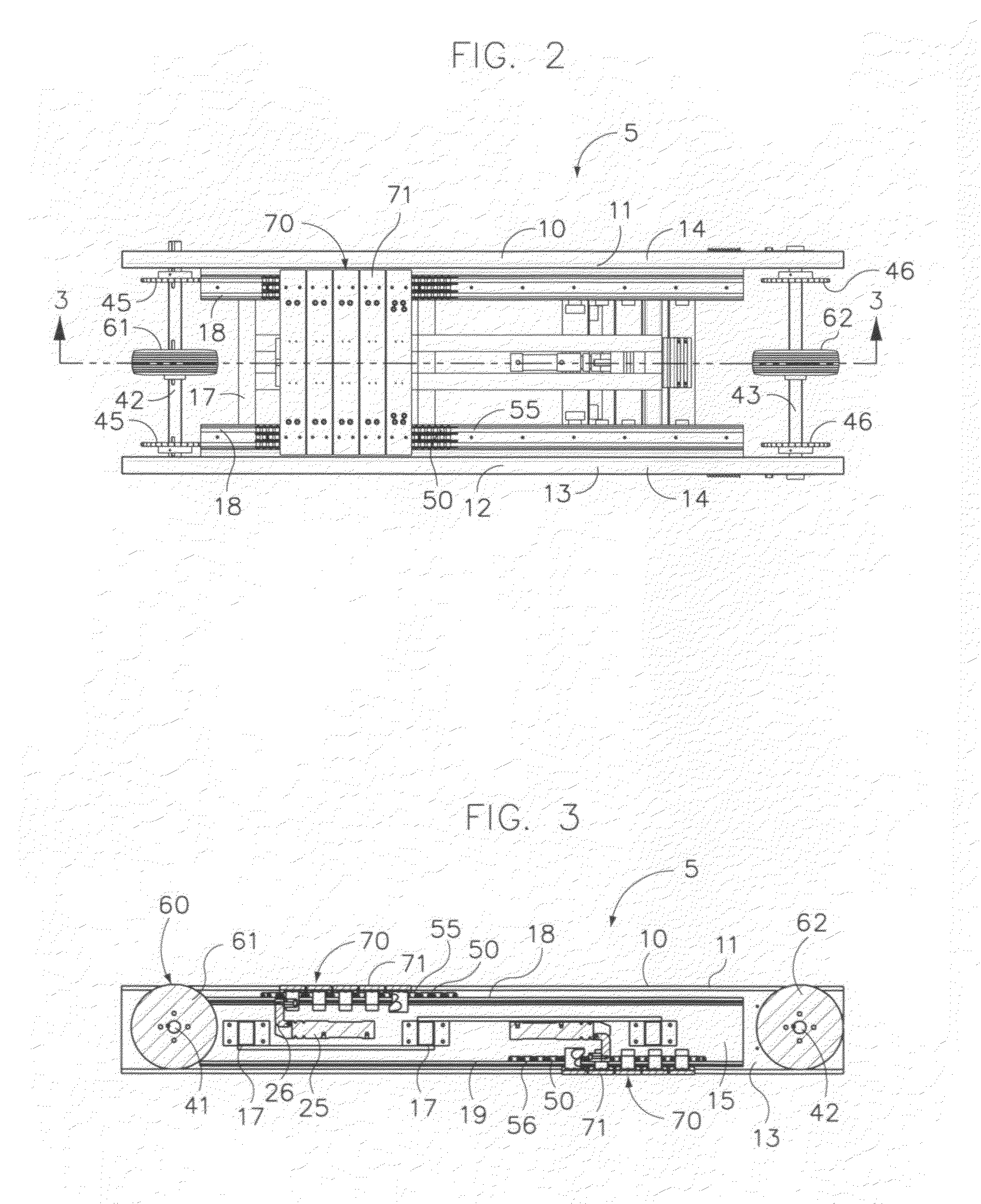
[0022]The present invention pertains to a low profile, asynchronous, accumulating over-under conveyor generally depicted by reference number 5 in FIGS. 1 and 2. The conveyor 5 uses two continuously moving chain loops 50 that form upper and lower tracks on which flexible work platforms 70 ride. When one of the platforms 70 reaches the end of one track, it frictionally engages and flexibly compresses a pneumatic wheel drive 60. The platform 70 also flexes to negotiate a low profile inversion and return on the other track. This allows the conveyor 5 to handle long work platforms ...


PUM


Abstract

This invention is a low profile, over-under conveyor with two continuously moving chain loops that form upper and lower tracks on which flexible work platforms ride. Each flexible platform includes two or more spaced metal slats joined by a thin flexible band. The slats include shoes that rest on and frictionally engage the moving chain loops. When one of the platforms reaches the end of one track, the flexible platform frictionally engages and compresses a pneumatic drive wheel and flexes to negotiate a low profile inversion and return on the other track. This allows the conveyor to handle long work platforms, while having a relatively low profile. Asynchronous accumulation and release of the freely moving flexible work platforms is accomplished using stop cylinders mounted inside the frame of the conveyor.

Description

TECHNICAL FIELD OF THE INVENTION[0001]This invention relates to a low profile over-under conveyor with a chain drive for same level movement of flexible work platforms, and a wheel drive for engaged rotational over-under movement of those flexible work platforms.BACKGROUND OF THE INVENTION[0002]Accumulating over-under conveyors are well known. These conveyors use chain loops that form tracks for supporting pallets that ride along tracks. The pallets have shoes for engaging the chain loops that form upper and lower tracks. The shoes engage the outside of the chain loop when traveling along the upper track, and the inside of the chain loop when traveling along the lower track. Examples of some over / under conveyor designs are disclosed in U.S. Pat. Nos. 5,495,933 and 5,407,058. These conveyor designs use two loops of triple roller strand conveyor chain that pass around sprocket assemblies. The head sprocket assembly includes a drive sprocket wheel. A series of pallets are positioned at...

Claims


Application Information

Patent Timeline
Patent Type & Authority Patents(United States)
IPC IPC(8): B65G47/34
CPCB65G17/002
Inventor CANNELL, JOHN DANA
Owner ZETA GRP MFG LLC
Why Eureka
Try Eureka